
Road surface illumination device

A lighting device and driving circuit technology, applied in the field of laser applications, can solve the problems of large size of LED chips, uneven illuminance distribution, poor image clarity, etc.

Inactive Publication Date: 2018-12-28
BEIJING UNIV OF TECH
View PDF9 Cites 1 Cited by
  • Summary
  • Abstract
  • Description
  • Claims
  • Application Information

AI Technical Summary

Problems solved by technology

[0003] In recent years, the technology of using LED as a monitoring supplementary light for supplementary light has been widely used in the security field, but there are still some shortcomings in the LED light source. For example, the LED chip is not only large in size and low in luminous efficiency, but also has a large beam divergence angle and a Poor collimation results in a limited irradiation distance of the LED light source, which can only cover a short horizontal distance range when used to supplement light for surveillance cameras, and is only suitable for short-distance supplementary light
[0004] To achieve clear imaging within a certain horizontal distance, not only the irradiation distance of the monitoring fill light needs to be increased, but the light intensity of the monitor fill light also needs to meet certain requirements. The power and light intensity are also fixed, which leads to uneven distribution of illuminance received at different horizontal distances. The illuminance received at the closer horizontal distance to the light source is stronger, while the illuminance received at a farther horizontal distance from the light source is weaker. The image clarity in the monitoring screen is poor

Method used


Image

  • Road surface illumination device
  • Road surface illumination device
  • Road surface illumination device

Examples


Embodiment Construction

[0032] In order to make the purpose, technical solutions and advantages of the embodiments of the present invention clearer, the technical solutions in the embodiments of the present invention will be clearly and completely described below in conjunction with the drawings in the embodiments of the present invention. Obviously, the described embodiments It is a part of embodiments of the present invention, but not all embodiments. Based on the embodiments of the present invention, all other embodiments obtained by persons of ordinary skill in the art without creative efforts fall within the protection scope of the present invention.

[0033] In the existing technology, in the field of video surveillance, if the surveillance camera is to achieve clear imaging within a certain horizontal distance range, not only the irradiation distance of the surveillance supplementary light needs to be increased, but the light intensity of the surveillance supplementary light also needs to meet ...


PUM


Abstract

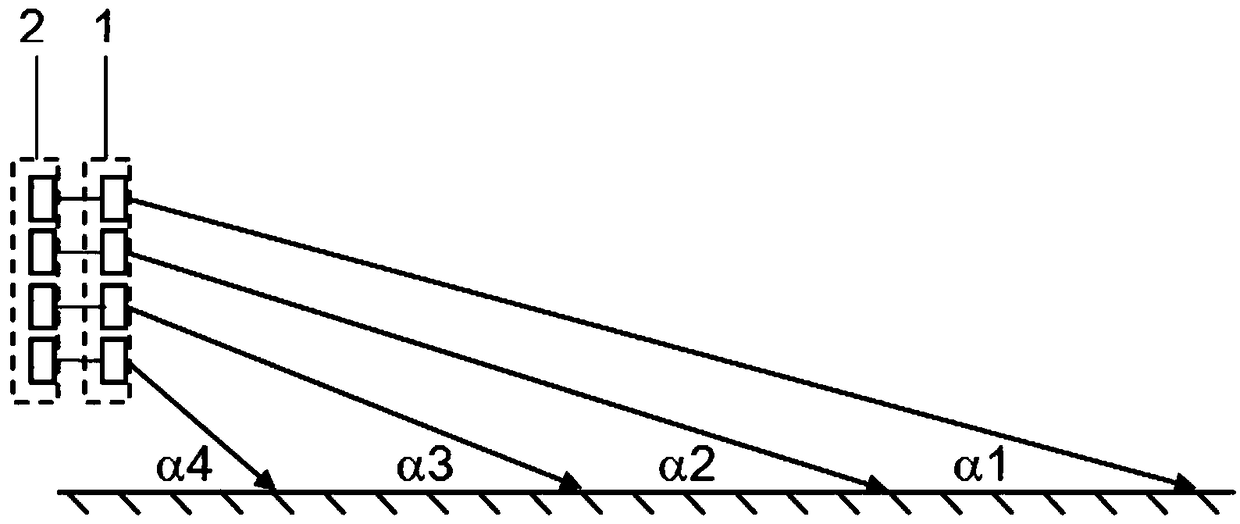
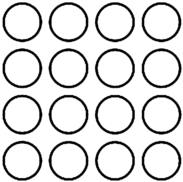
The embodiment of the invention provides a road surface illumination device. The road surface illumination device comprises two-dimensional semiconductor laser light source arrays and a light source array driving circuit, wherein the two-dimensional semiconductor laser light source arrays are arranged on a plane perpendicular to the length direction of the road surface, the included angle betweenthe laser output direction of each semiconductor laser light source in the two-dimensional semiconductor laser light source arrays and a horizontal plane is increased along with the decrease of the height which the distance from a line positioned by the included angle to the road surface; a light source driving circuit array comprises a plurality of driving circuits, the semiconductor laser lightsources in the same line are corresponding to the driving circuits, the driving circuits are used for changing a laser output power of the semiconductor laser light sources in the corresponding line.Uniform illumination on the road surface can be realized by arranging the two-dimensional semiconductor laser light source arrays and the corresponding driving circuits, so that uniform light supplementation can be provided for a monitoring camera within a certain horizontal distance range, the problem that a monitoring light supplementing lamp cannot realize uniform illumination in the prior artis solved.

Description

technical field [0001] Embodiments of the present invention relate to the technical field of laser applications, and more specifically, to road lighting devices. Background technique [0002] At present, video surveillance is an important part of the security field. Surveillance images also play an increasingly obvious role in many applications. For example, with the increase of traffic vehicles on the road, in order to prevent traffic accidents and be able to Effective and rapid handling of accidents requires video monitoring of road traffic conditions to obtain monitoring images. The demand for long-distance clear imaging is also increasingly strong, so a road lighting device is needed to supplement light for the image capture of the surveillance camera to achieve longer-distance monitoring. [0003] In recent years, the technology of using LED as a monitoring supplementary light for supplementary light has been widely used in the security field, but there are still some ...

Claims


Application Information

Patent Timeline
IPC IPC(8): F21S8/00F21V5/04F21V19/00F21V23/02F21Y115/10
CPCF21S8/00F21V5/04F21V19/001F21V23/003F21V23/02F21Y2115/10
Inventor 刘友强赵帆曹银花王智勇
Owner BEIJING UNIV OF TECH
Learn More