Hydraulic retarder rotor with blades with automatically adjustable inclination angles

A hydraulic retarder and automatic adjustment technology, applied in the direction of brake type, brake components, hydraulic resistance brake, etc., can solve the problem of increasing energy waste and other problems

Active Publication Date: 2018-12-28
JILIN UNIV
View PDF6 Cites 3 Cited by
  • Summary
  • Abstract
  • Description
  • Claims
  • Application Information

AI Technical Summary

Problems solved by technology

However, with the increase of the liquid filling amount, the energy waste caused by the oil return process will also increase, and it is urgent to find another automatic adjustment method to reduce the energy loss.

Method used


Image

  • Hydraulic retarder rotor with blades with automatically adjustable inclination angles
  • Hydraulic retarder rotor with blades with automatically adjustable inclination angles
  • Hydraulic retarder rotor with blades with automatically adjustable inclination angles

Examples


Embodiment Construction

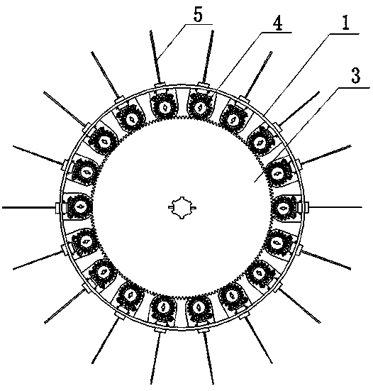
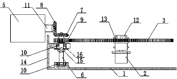
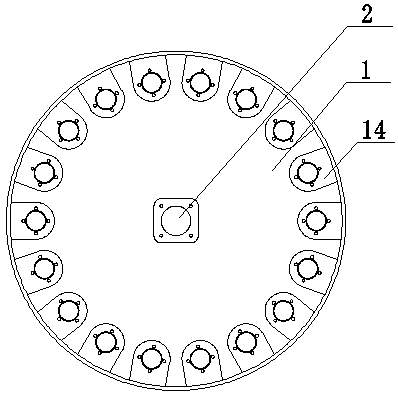
[0025] see Figure 1-Figure 6 Shown:

[0026] A hydraulic retarder rotor whose blade inclination can be automatically adjusted, including a base 1, a motor 2, a large gear 3, 18 planetary gear assemblies 4, and blades 5, the motor 2 is arranged at the center of the base 1, and the large gear 3 Coaxially connected with the output shaft of the motor 2, 18 planetary gear assemblies 4 are equidistantly arranged on a circle of the bull gear 3, and the planetary gear assembly 4 includes a bevel gear shaft 6, an input bevel gear 7, and an output bevel gear 8 And the pinion 9, the bevel gear shaft 6 is connected on the base 1 through the bearing 10, the bevel gear shaft 6 is arranged parallel to the output shaft of the motor 2, the input bevel gear 7 is arranged at the upper end of the bevel gear shaft 6, the output bevel gear 8 is connected with the The input bevel gear 7 is meshed, the pinion 9 and the input bevel gear 7 are coaxially fixed on the bevel gear shaft 6, the pinion 9 i...


PUM


Abstract

The invention relates to a hydraulic retarder rotor with blades with automatically adjustable inclination angles, and aims to change a brake effect of the hydraulic retarder by automatically adjustingthe inclination angles of rotor blades according to different brake requirements identified by a sensor. The hydraulic retarder rotor with the blades with the automatically adjustable inclination angles comprises a base, a motor, a large gear, a plurality of planetary wheel assemblies and the blades; the motor is arranged in the centre of the base; the large gear is coaxially connected with an output shaft of the motor; the plurality of the planetary wheel assemblies are arranged on the periphery of the large gear at equal distance; shaft holes are formed in the side wall of the base at equaldistance; a blade shaft is arranged at one end of each blade; the blade shafts penetrate through the shaft holes in the side wall of the base and are coaxially connected with output bevel gears of the planetary wheel assemblies; and all blades are arranged in the radial direction of the large gear at equal distance. The hydraulic retarder rotor with the blades with the automatically adjustable inclination angles has the main effects of changing a brake torque signal into inclination angle information automatically according to a received signal of a torque sensor, and adjusting the degrees ofthe inclination angles of the blades by controlling the rotating of the motor.

Description

technical field [0001] The invention relates to a retarder rotor, in particular to a hydraulic retarder rotor whose vane inclination angle can be automatically adjusted. Background technique [0002] The hydraulic retarder is a kind of retarder that reduces the speed of the vehicle through a hydraulic device, and has its unique advantages especially in the process of braking the car downhill. Its main working principle is that the rotation of the rotor drives the rotation of the liquid, thereby generating a certain impact force on the stator. According to the law of Newton's interaction force, it can be known that the rotor blade must be subject to a reaction force, and the braking torque generated by the reaction will provide a certain force. braking effect. [0003] Different road conditions need to provide different braking effects, so it is of great significance to study the automatic adjustment function of hydraulic retarder braking effect. In fact, there are many fac...

Claims


Application Information

Patent Timeline
IPC IPC(8): F16D57/02F16D65/00
CPCF16D57/02F16D65/00
Inventor 袁哲刘春宝刘琦
Owner JILIN UNIV
Why Eureka
Try Eureka