
Solar energy and wind force combined type power generating device for ships

A technology of power generation device and solar energy, which is applied in wind turbine combination, wind energy power generation, wind turbine and other directions, can solve the problems such as wind power generation device can only be fixed on ships, affects the normal use of ships, and is not conducive to the use of ships at sea, etc., and reaches the scope of application. Wide, easy to disassemble, save space

Active Publication Date: 2018-12-28
SHANDONG MINGCHUAN AUTOMOBILE GRP CO LTD
View PDF15 Cites 5 Cited by
  • Summary
  • Abstract
  • Description
  • Claims
  • Application Information

AI Technical Summary

Problems solved by technology

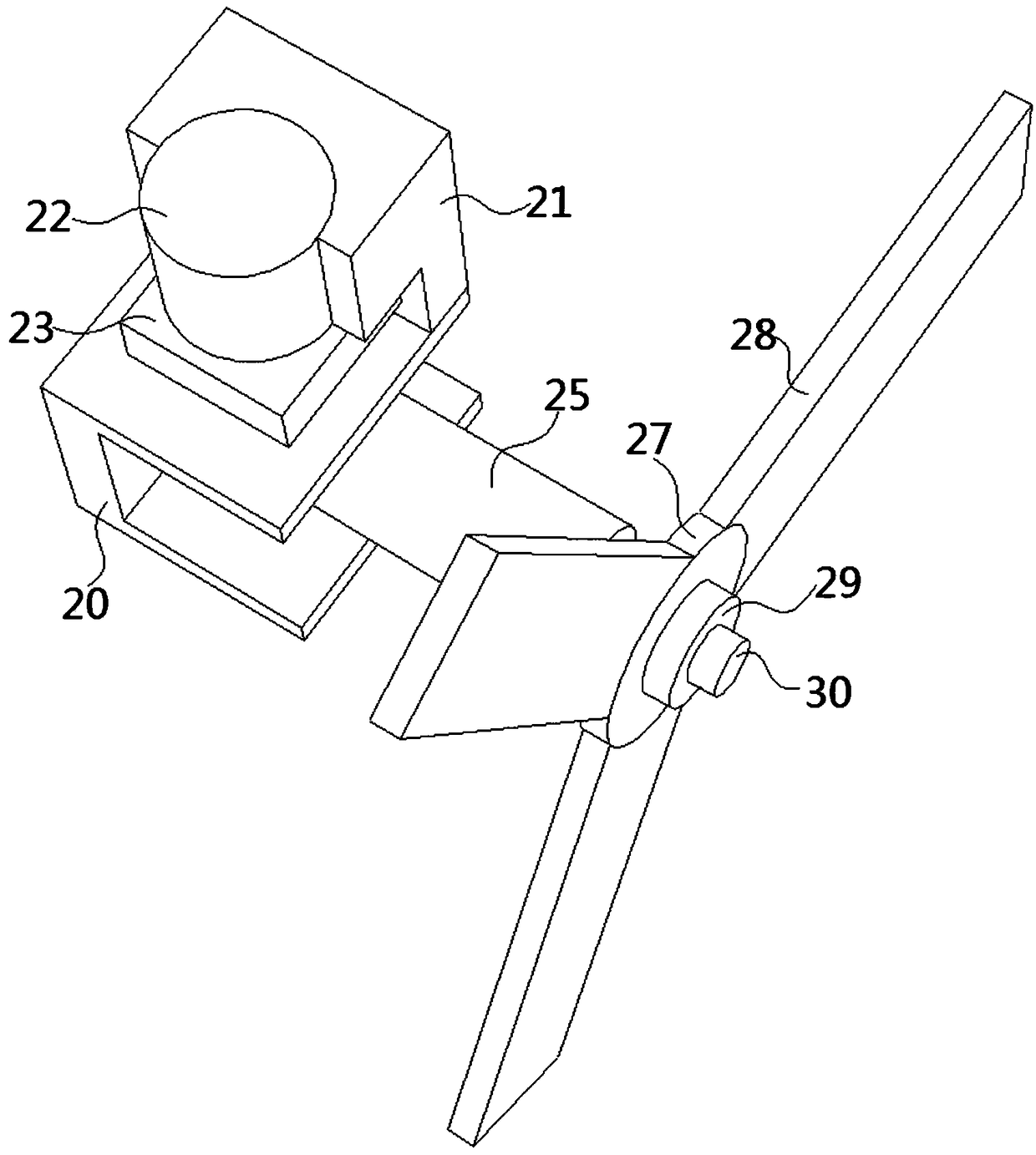
[0005] The purpose of the present invention is to provide a combined solar and wind power generating device for ships. The combined solar and wind power generating device for ships is fixed on the ship splint through the fixing plate, and the first support rod is rotated by controlling the first motor, and then Control the second motor to drive the power generation device to rotate, so that the fan blades are always facing the direction of the wind, so that the power generation effect is the best, suitable for ships, and easy to disassemble, which solves the problem that the existing wind power generation devices generally cannot rotate the fan blades. It is beneficial to the use of ships at sea, and the existing wind power generation device can only be fixed on the ship, which will affect the normal use of the ship

Method used


Image

  • Solar energy and wind force combined type power generating device for ships
  • Solar energy and wind force combined type power generating device for ships
  • Solar energy and wind force combined type power generating device for ships

Examples


Embodiment Construction

[0031] The following will clearly and completely describe the technical solutions in the embodiments of the present invention with reference to the accompanying drawings in the embodiments of the present invention. Obviously, the described embodiments are only some, not all, embodiments of the present invention. Based on the embodiments of the present invention, all other embodiments obtained by persons of ordinary skill in the art without creative efforts fall within the protection scope of the present invention.

[0032] see Figure 1-9 As shown, the present invention is a combined solar and wind power generation device for ships, including a base plate 1, a first support rod 7 and an electric slider 15, a group of chute 18 is opened on the side of the first support rod 7, and the electric slider 15 is slidably matched with the first support rod 7, and a group of sliders 16 are fixed on the inner wall of the electric slider 15, and the slider 16 is slidably matched with the ...


PUM


Abstract

The invention discloses a solar energy and wind force combined type power generating device for ships, and relates to the technical field of new energy. The solar energy and wind force combined type power generating device comprises a base plate, a first supporting rod and an electric sliding block. A group of sliding grooves is formed in the lateral circumference face of the first supporting rod.The electric sliding block is in sliding-fit with the first supporting rod. A group of sliding blocks is fixed to the inner wall of the electric sliding block. The sliding blocks are in sliding-fit with the sliding grooves. A plurality of first groove holes are formed in the surface of the electric sliding block. The inner walls of the first groove holes are rotatably connected with third connecting rods by rotating shafts. Through fixing plates, the solar energy and wind force combined type power generating device the ships can be fixed to a ship clamping plate. Through controlling a first motor, the first supporting rod rotates, and further a second motor is controlled to drive the power generating device to rotate, and therefore fan blades always face the wind direction, and the powergenerating effect can be optimized. Through controlling the electric sliding block to slide along the surface of the first supporting rod, the function of being foldable and retractable of a solar energy power generating panel can be achieved.

Description

technical field [0001] The invention belongs to the technical field of new energy sources, in particular to a combined solar and wind power generating device for ships. Background technique [0002] Wind power refers to converting the kinetic energy of wind into electrical energy. Wind is a non-polluting energy source. Using wind power to generate electricity is very environmentally friendly and can generate huge amounts of electricity. Therefore, more and more countries pay more attention to wind power generation. As a clean and renewable energy, wind energy has been paid more and more attention by countries all over the world. Its reserves are huge, 10 times larger than the total amount of water energy that can be developed and utilized on the earth. The wind has been used by people for a long time-mainly through windmills to pump water, grind flour, etc., but now, people are interested in how to use wind to generate electricity. [0003] The energy of solar energy is t...

Claims


Application Information

Patent Timeline
IPC IPC(8): F03D9/11F03D9/32F03D7/02H02S10/12H02S20/30
CPCF03D7/0204F03D9/007F03D9/11F03D9/32H02S10/12H02S20/30Y02E10/50Y02E10/72Y02E10/728Y02E70/30
Inventor 王正阳
Owner SHANDONG MINGCHUAN AUTOMOBILE GRP CO LTD
Learn More