
Efficient printing and dyeing wastewater aeration treatment device

A technology of printing and dyeing wastewater and treatment device, which is applied in the textile industry wastewater treatment, water aeration, water/sewage treatment and other directions, can solve the problems of high chroma, harm to human health and living environment, low treatment efficiency, etc., to increase oxygen The concentration, the treatment effect is obvious, the effect of increasing the aeration effect

Inactive Publication Date: 2018-12-28
宛兴友
View PDF5 Cites 1 Cited by
  • Summary
  • Abstract
  • Description
  • Claims
  • Application Information

AI Technical Summary

Problems solved by technology

The sources of printing and dyeing wastewater and the components of pollutants are very complex, with the characteristics of large changes in water quality, high organic content, high chroma (mainly colored dyes), etc. Direct discharge will bring great harm to human health and the living environment, and cause water resources. waste
As the country and society pay more and more attention to environmental protection requirements and the requirements for sustainable development, traditional processing methods have become increasingly difficult to meet the requirements of production and environmental protection
[0003] At present, the more practical treatment method is to use aeration, but due to the large amount of water in printing and dyeing sewage, a single aeration method is difficult to meet the demand for oxygen content in sewage, and the efficiency of retreatment after aeration is low , cannot meet the usage requirements, so it is necessary to optimize and upgrade the existing traditional equipment to meet the usage requirements

Method used


Image

  • Efficient printing and dyeing wastewater aeration treatment device
  • Efficient printing and dyeing wastewater aeration treatment device
  • Efficient printing and dyeing wastewater aeration treatment device

Examples


Embodiment Construction

[0020] The technical solution of this patent will be further described in detail below in conjunction with specific embodiments.

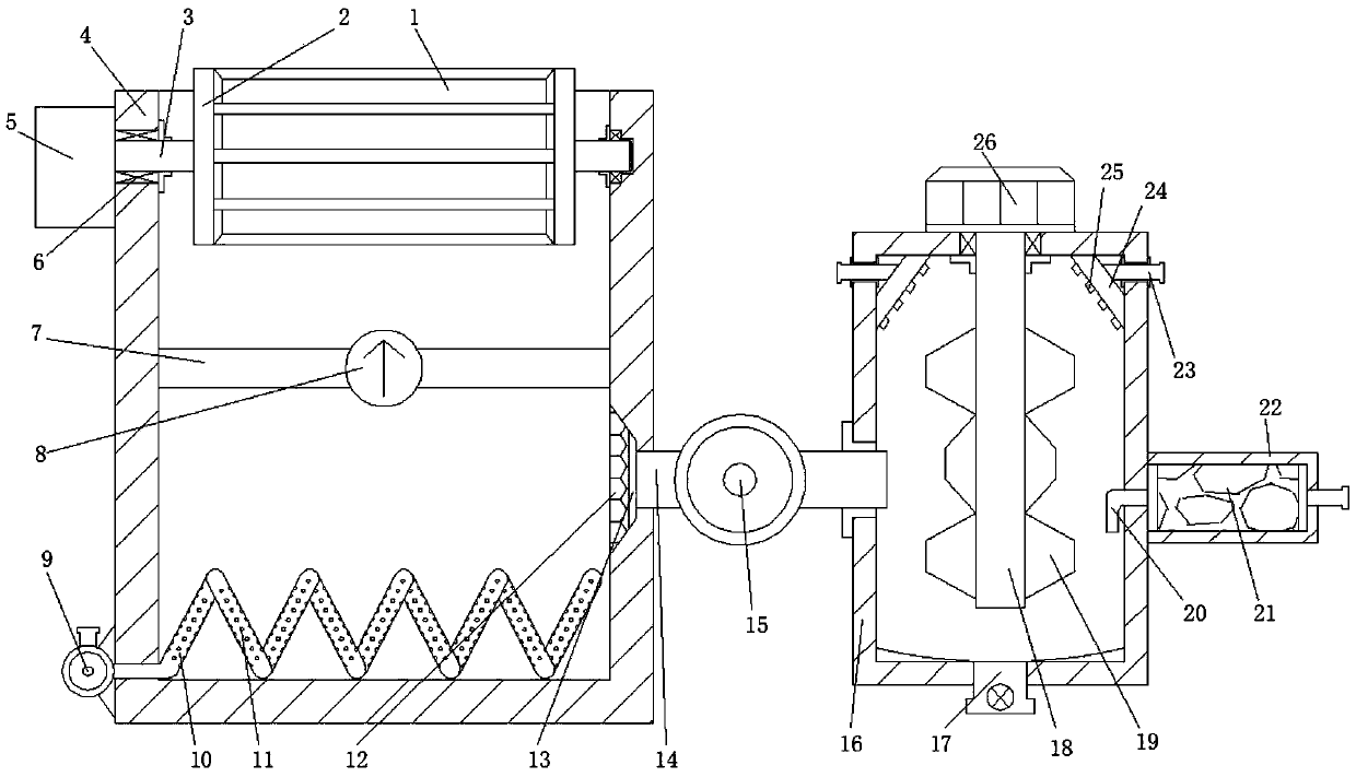
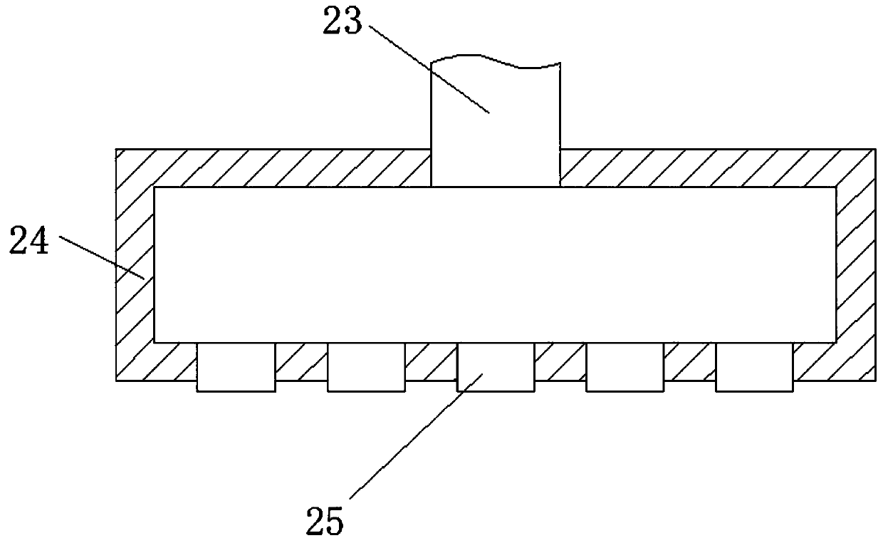
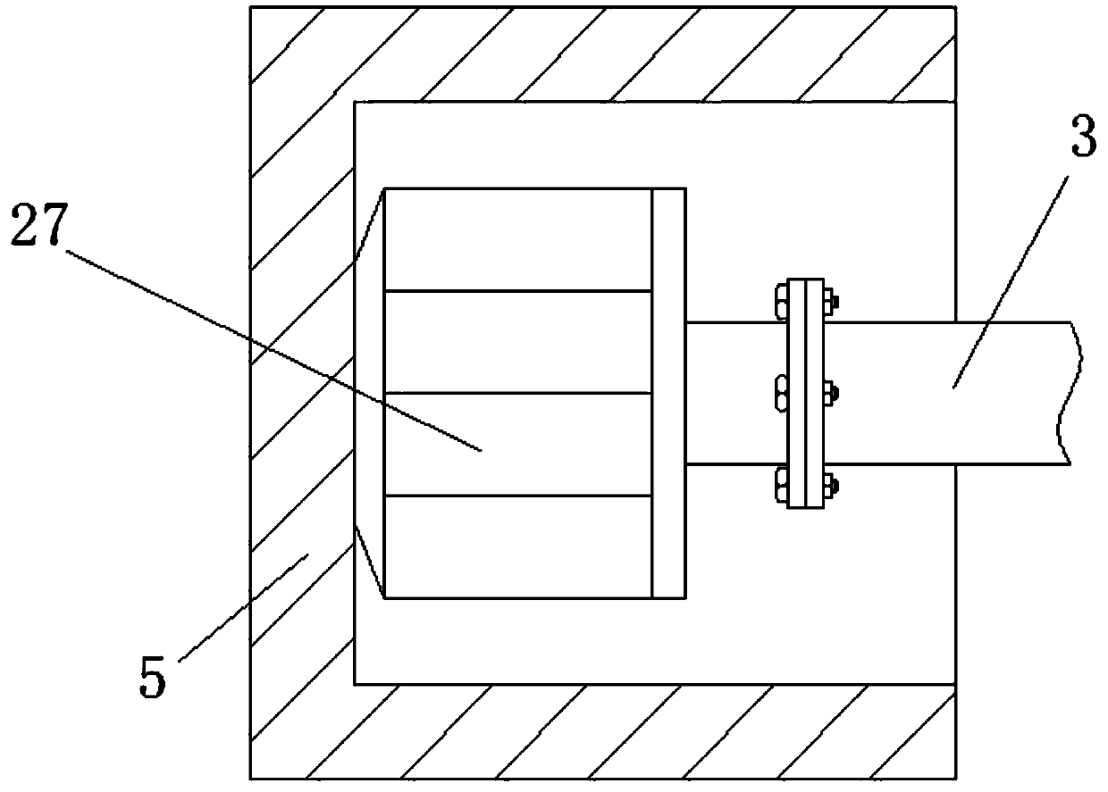
[0021] see Figure 1-4 A high-efficiency aeration treatment device for printing and dyeing wastewater, comprising an aeration tank 4; a transmission box 5 is installed on the upper left side outer wall of the aeration tank 4; a winch motor 27 is installed inside the transmission box 5 through bolts The left side of the hoisting motor 27 is connected and installed with the connecting shaft 3 through a coupling to provide rotational power; the connecting shaft 3 is connected and fixed in the upper inner wall of the aeration tank 4 through the connecting bearing 6 in the transverse direction, and the middle part is fixed The stirring wheel roller 2 is welded and driven by the winch motor 27 to rotate; the upper part of the stirring wheel roller 2 stretches out of the aeration tank 4, and the surface of the stirring wheel roller 2 is uniformly provided...


PUM


Abstract

The invention provides an efficient printing and dyeing wastewater aeration treatment device which comprises an aeration tank, wherein a transmission tank is connected with the outer wall of the upperpart of the left side of the aeration tank; a connecting shaft is transversely connected and fixed in the inner wall at the upper part of the aeration tank through a connecting bearing; stirring wheel rollers are fixedly welded in the middle of the connecting shaft; an aeration tube is connected with the right side of an air blower; a filtering net is arranged at the upper part on the right sideof the aeration tube; the filtering net is vertically connected and fixed inside a water sucking hole; the water sucking hole is formed in the inner wall of the right side of the aeration tank; the right side of the water sucking hole is accessed to a connecting tube; the connecting tube is accessed to a coagulation tank rightwards; a water sucking pump is connected and mounted in the middle of the connecting tube; the coagulation tank is arranged on the right side of the aeration tank; a stirring motor is connected and fixed on the outer wall at the upper part of the coagulation tank throughbolts; a stirring rod is vertically accessed to the coagulation tank; stirring blades are welded and fixed at the lower part of the stirring rod; a water conveying tube is accessed to an adsorption tank rightwards. The device is remarkable in overall treatment effect and good in practicability.

Description

technical field [0001] The invention relates to printing and dyeing wastewater treatment equipment, in particular to a high-efficiency aeration treatment device for printing and dyeing wastewater. Background technique [0002] The printing and dyeing industry is a typical water-intensive industry that consumes nearly 100 million tons of demineralized water for process every year. The sources of printing and dyeing wastewater and the composition of pollutants are very complex, with the characteristics of large changes in water quality, high organic content, high chroma (mainly colored dyes), etc. Direct discharge will bring great harm to human health and living environment, and cause water resources. waste. As the country and society pay more and more attention to environmental protection requirements and the requirements for sustainable development, traditional processing methods have become more and more difficult to meet the requirements of production and environmental pr...

Claims


Application Information

Patent Timeline
Patent Type & Authority Applications(China)
IPC IPC(8): C02F9/04C02F103/30
CPCC02F1/283C02F1/5281C02F7/00C02F9/00C02F2103/30
Inventor 宛兴友
Owner 宛兴友
Learn More