
Plastic injection mold

An injection mold and plastic technology, which is applied in the field of plastic injection molds, can solve the problems of adjusting the discharge speed and complex structure, and achieve the effect of precise injection molding.

Inactive Publication Date: 2018-12-28
CIXI JINGCHENG MOLD
View PDF0 Cites 1 Cited by
  • Summary
  • Abstract
  • Description
  • Claims
  • Application Information

AI Technical Summary

Problems solved by technology

[0002] Plastic injection molding needs to adjust the discharge speed according to the size or precision of the injection molded part. Existing plastic injection molds have a complex structure for adjusting the discharge speed

Method used


Image

  • Plastic injection mold
  • Plastic injection mold
  • Plastic injection mold

Examples


Embodiment Construction

[0019] The present invention will be described in further detail below in conjunction with the accompanying drawings, but it should not be understood that the scope of the above-mentioned theme of the present invention is limited to the above-mentioned embodiments.

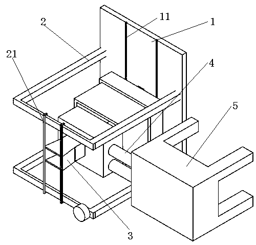
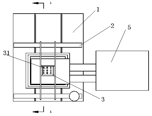
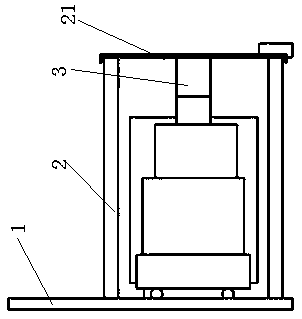
[0020] Such as Figure 1-6 As shown, a plastic injection mold includes a base plate 1, a bracket 2, an injection molding mechanism 4 and a receiving bin 5, the bracket 2 is installed on the base plate 1, the bottom of the injection molding mechanism 4 is provided with rollers, and the top of the bracket 2 is provided with two parallel The guide rail 21, the bottom plate 1 is provided with a guide groove 11 at the corresponding position of the roller, the left side of the injection molding mechanism is provided with a receiving bin 5, and the receiving bin 5 is used to collect the injection molded plastic parts, and the top of the injection molding mechanism 4 is provided with a feeding hopper 3, The upper part of ...


PUM


Abstract

The invention relates to a plastic injection mold. The plastic injection mold comprises a bottom plate, a support, an injection molding mechanism and a material collecting bin, wherein the support isarranged on the bottom plate, a idler wheel is arranged at the bottom of the injection molding mechanism, two parallel guide rails are arranged at the top of the support, a guide groove is formed in the position, corresponding to the idler wheel, of the bottom plate, the material collecting bin is arranged on the left side of the injection molding mechanism, the material collecting bin is used forcollecting plastic parts after injection molding, a feeding hopper is arranged at the top of the injection molding mechanism, and the upper part of the feeding hopper is slidably mounted on the guiderails; and the feeding hopper is of a V-shaped structure with a wide upper part and a narrow lower part, a feeding hopper discharging plate in the middle of the feeding hopper is provided with discharging holes which are larger than the size of plastic particles, a filter plate is slidably arranged at the bottom of the feeding hopper discharging plate, and the filter plate is provided with filterholes which are not smaller than the size of the discharging holes at the positions, corresponding to the discharging holes. According to the plastic injection mold, the filter plate is slid in a left-right mode, so that overlapping areas of the discharging holes and the filter holes are changed, discharging speed of a discharging hopper is adjusted, and accurate injection molding processing is achieved.

Description

technical field [0001] The invention relates to a plastic injection mold. Background technique [0002] Plastic injection molding needs to adjust the discharge speed according to the size or precision of the injection molded part. The existing plastic injection mold has a complex structure for adjusting the discharge speed. Contents of the invention [0003] In order to solve the deficiencies in the prior art, the invention provides a plastic injection mold with simple structure and convenient use, which can adjust the discharge speed. [0004] A plastic injection mold in the present invention includes a bottom plate, a bracket, an injection molding mechanism and a material receiving bin, the bracket is installed on the bottom plate, rollers are provided at the bottom of the injection molding mechanism, two parallel guide rails are arranged on the top of the bracket, and the bottom plate is at the position corresponding to the rollers There is a guide groove, and there is...

Claims


Application Information

Patent Timeline
Patent Type & Authority Applications(China)
IPC IPC(8): B29C45/18B29B13/10
CPCB29C45/18B29B13/10
Inventor 徐国良
Owner CIXI JINGCHENG MOLD
Learn More