
A fully automatic assembly line for oil pump accessories

An assembly line, fully automatic technology, applied in the direction of metal processing equipment, metal processing, manufacturing tools, etc., can solve the problems of low assembly efficiency, high spring difficulty, and spring compression not reaching the preset value, so as to reduce labor intensity, Improve the assembly accuracy and eliminate the effect of uneven compression

Active Publication Date: 2019-10-25
CHANGXING BEST MASCH CO LTD
View PDF6 Cites 0 Cited by
  • Summary
  • Abstract
  • Description
  • Claims
  • Application Information

AI Technical Summary

Problems solved by technology

[0005] 1) Since when the spring is transferred to the spring installation groove of the oil pump, the receiving seat is only placed on the end face of the oil pump housing without any connection structure, so it is easy to remove the receiving seat when the spring is transferred. The phenomenon of slipping occurs, which causes the spring to not be smoothly transferred to the spring installation groove on the oil pump, which in turn leads to low assembly efficiency;
[0006] 2) In addition, after the spring is compressed by the pressure block, both the adjustment bolt and the pressure block are subjected to the reaction force of the spring, and when the spring is knocked into the spring installation groove on the oil pump, the vibration generated by the knock will make the adjustment bolt in the spring Under the action of the reaction force, the receiving seat is unscrewed, so that the spring is not compressed enough before it enters the spring installation groove on the oil pump. In other words, the compression of the spring does not reach the preset length. As a result, the spring cannot fully enter the spring installation groove of the oil pump, and the adjusting bolt has to be screwed in again until the compression of the spring reaches the preset span, which affects the assembly efficiency
[0009] 1. The spring still needs to be manually placed in the compression groove by the worker, but the space between the compression groove and the pressing block is narrow, and the manual placement of the spring is difficult and the accuracy is low;
[0010] 2. The two ends of the spring are not supported or limited. Due to the uneven force applied during the extrusion process, it is easy to cause the spring to tilt during the compression process. As a result, when the spring is pressed into the spring installation groove, due to the spring tilt , causing the spring to pop out of the spring mounting groove, and the installation fails

Method used


Image

  • A fully automatic assembly line for oil pump accessories
  • A fully automatic assembly line for oil pump accessories
  • A fully automatic assembly line for oil pump accessories

Examples


Embodiment 1

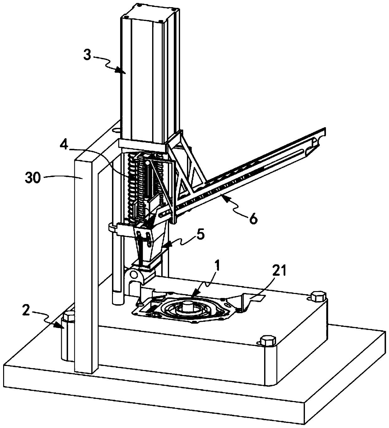
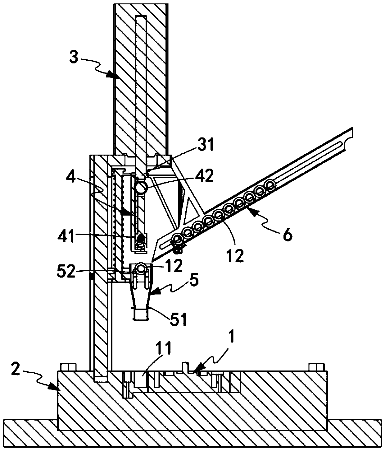
[0077] Such as figure 1 , figure 2 , Figure 4 and Figure 11 As shown, a fully automatic assembly line for oil pump accessories, which includes a pump body 1, a spring installation groove 11 is arranged on the pump body 1, and the spring installation groove 11 is used for installing a spring 12, and also includes:

[0078] Mounting seat 2, the mounting seat 2 is provided with a placing groove 21 that is shaped like the pump body 1, the pump body 1 is placed in the placing groove 21, and the spring mounting groove 11 is exposed horizontally;

[0079] Push the cylinder 3, the push cylinder 3 is installed above the mounting seat 2 through the gantry frame 30, and the push end 31 of the push cylinder 3 is vertically pushed downwards vertically to the spring installation groove 11;

[0080] Spring pushing mechanism 4, described spring pushing mechanism 4 is arranged on the pushing end 31 of described pushing cylinder 3, and it pushes described spring 12 by described pushing cy...

Embodiment 2

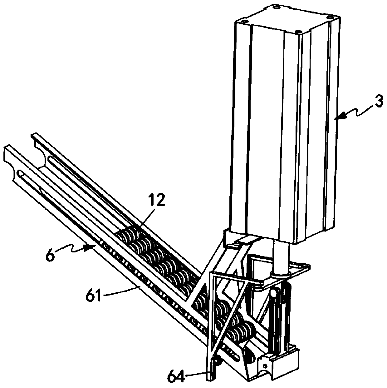
[0113] Figure 17 It is a structural schematic diagram of Embodiment 2 of a fully automatic assembly line for oil pump accessories of the present invention; Figure 17 As shown, the parts that are the same as or corresponding to those in Embodiment 1 use the reference numerals corresponding to Embodiment 1. For the sake of simplicity, only the differences from Embodiment 1 will be described below. This embodiment two and figure 1 The difference of the shown embodiment one is:

[0114] Such as Figure 17 As shown, a fully automatic assembly line for oil pump accessories, the spring pushing mechanism 4 also includes a rotating assembly 42 driven to rotate by the pushing cylinder 3, when the pushing block 41 pushes the spring 12, the rotating assembly 42 The springs 12 are driven to rotate synchronously.

[0115] Such as Figure 18 , Figure 19 and Figure 20 As shown, wherein, the rotating assembly 42 includes:

[0116] Rotating roller 43, said rotating roller 43 is arra...


PUM


Abstract

The invention relates to the technical field of oil pump assembling, and provides a full-automatic assembling production line of an oil pump accessory. The full-automatic assembling production line comprises a mounting seat, a pushing cylinder, a spring pushing mechanism, a compression mechanism and an automatic input mechanism. The pushing cylinder squeezing a spring is reset to drive a limitingpiece to rotate, so that the limiting piece loses limitation to the spring in a rail; at every time when the pushing cylinder is reset, the limiting piece rotates to output one spring into a compression slot, so that the technical problem that the spring is automatically input into the compression slot in a spring assembling process is solved; the springs can be orderly and automatically input into the compression slot one by one; manual placement is avoided; the assembling precision is improved; the labor intensity is reduced; and furthermore, in the spring compressing and assembling process,a bearing assembly horizontally supports the spring to keep the horizontalness of the spring and avoid the spring from tilting.

Description

technical field [0001] The invention relates to the technical field of oil pump assembly, in particular to a fully automatic assembly line for oil pump accessories. Background technique [0002] When the automobile engine is working, each moving part acts on another part with a certain force, and high-speed relative motion occurs. With relative motion, friction will inevitably occur on the surface of the parts, thereby accelerating wear. Therefore, in order to reduce wear and tear, reduce friction resistance and prolong service life, there must be lubrication system parts on the engine. The main components of the lubrication system are various equipment such as an oil pump. The function of the oil pump is to increase the oil to a certain pressure and then forcefully send it to the moving surface of each part of the engine. It generally includes a pump cover and a pump body. It is connected with the pump body by screws, and the pump body is equipped with an inner rotor, an o...

Claims


Application Information

Patent Timeline
Patent Type & Authority Patents(China)
IPC IPC(8): B23P19/04
CPCB23P19/001B23P19/048
Inventor 丁震华
Owner CHANGXING BEST MASCH CO LTD
Learn More