Multifunctional display cabinet

A display cabinet and multi-functional technology, which is applied to display cabinets, applications, display stands, etc., can solve the problems such as the inability to adjust the angle of the fill light, the inability to charge the mobile phone, and the cluttered lines, so as to achieve convenient lines. It has the effect of easy laying, convenient transportation and transfer, and improved sealing effect.

Inactive Publication Date: 2018-12-28
FOSHAN QIANGWEI NEW ENERGY TECH CO LTD
View PDF8 Cites 2 Cited by
  • Summary
  • Abstract
  • Description
  • Claims
  • Application Information

AI Technical Summary

Problems solved by technology

[0006] Aiming at the deficiencies of the prior art, the present invention provides a multi-functional display cabinet, which uses a split structure to facilitate disassembly of the support bar and the cross bar, and connects the support bar and the cross bar through the cooperation of the connecting pile and the connection hole, and the glass passes through the groove Fixed, it solves the problem that it is not easy to disassemble with glue, and it is convenient for the display cabinet to move to the field. The display cabinet is powered, and the line is fixed through the cable slot, which solves the problem of messy lines inside the display cabinet and facilitates the laying of the line. The USB charging port solves the problem that the mobile phone cannot be charged. The exhibits are lifted and placed on the tray. to improve the overall airtightness of the display cabinet

Method used


Image

  • Multifunctional display cabinet
  • Multifunctional display cabinet
  • Multifunctional display cabinet

Examples


Embodiment Construction

[0035] The following will clearly and completely describe the technical solutions in the embodiments of the present invention with reference to the accompanying drawings in the embodiments of the present invention. Obviously, the described embodiments are only some, not all, embodiments of the present invention. Based on the embodiments of the present invention, all other embodiments obtained by persons of ordinary skill in the art without making creative efforts belong to the protection scope of the present invention.

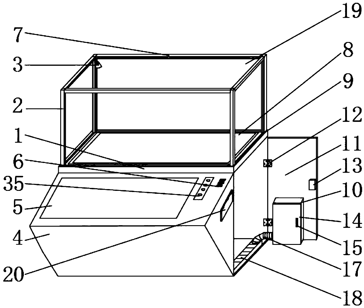
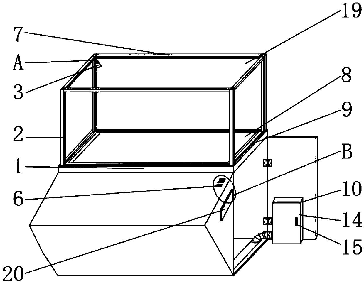
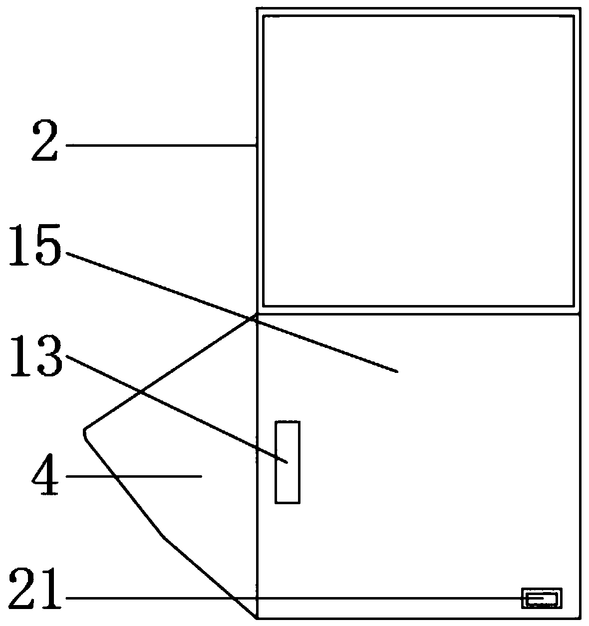
[0036] see Figure 1-9 , a multifunctional display cabinet, comprising a main body support 1, the outer surface of the upper end of the main body support 1 is provided with a groove 9 and a fixing hole 33, and the fixing hole 33 is arranged on one side of the groove 9, and the number of the fixing holes 33 is four group, the fixing holes 33 are all distributed on the four corners of the upper outer surface of the main body bracket 1, and the number of grooves 9 ...


PUM


Abstract

The invention relates to the technical field of display tools and discloses a multifunctional display cabinet, comprising a main support. The outer surface of the upper end of the main support is provided with a plurality of groups of channels and four groups of fixing holes; the fixing holes are arranged on one side of the channels; the fixing holes are evenly arranged in the four corners of theouter surface of the upper end of the main support; the four groups of channels distributed in the outer surface of the upper end of the main support are in rectangular distribution; the upper end, close to the fixing holes, of the upper outer surface of the main support is provided with support rods. The multifunctional display cabinet has the advantages that the split structure is used to facilitate disassembly of the support rods and transverse rods and facilitate carrying and transferring of the cabinet herein, the angle of supplementary lights is convenient to adjust, circuit laying is facilitated, and disordering of inner circuits in the cabinet is avoided; cellphones can be charged when tourists enjoy the sight, exhibits are lifted and placed in via a tray, and the integral tightness of the cabinet is improved.

Description

technical field [0001] The invention relates to the technical field of display appliances, in particular to a multifunctional display cabinet. Background technique [0002] The display cabinet is a protective display stand provided for commodity display. The color can be selected according to the shop decoration. The display cabinet has firm structure, easy disassembly and assembly, and convenient transportation. It is widely used in company exhibition halls, exhibitions, department stores, advertisements, etc., and is widely used in handicrafts, gifts, jewelry, mobile phones, glasses, clocks, tobacco, alcohol, cosmetics, etc. . [0003] In order to attract and attract customers to the greatest extent, the production of display cabinets must give full play to the designer's creative talent and rich imagination to create an unconventional aesthetic image. At the same time, we must pay attention to the authenticity of aesthetic creation in the production, that is, the infor...

Claims


Application Information

Patent Timeline
Patent Type & Authority Applications(China)
IPC IPC(8): A47F3/00A47F7/02H02J7/00
CPCA47B2220/0091A47F3/001A47F3/004A47F7/02H02J7/00
Inventor 管慧玲
Owner FOSHAN QIANGWEI NEW ENERGY TECH CO LTD
Why Eureka
Try Eureka