
An acoustic insulation device for a transformer

A transformer and sound insulation technology, which is applied in the direction of transformer/inductor noise damping, etc., can solve the problems that the sound insulation requirements of outdoor transformers cannot be met, the sound insulation effect is not obvious, and the sound insulation effect is limited, so as to achieve good acoustic sealing effect and easy Transport and installation, improve the effect of sound insulation performance

Active Publication Date: 2018-12-25
GLOBAL ENERGY INTERCONNECTION RES INST CO LTD +3
View PDF2 Cites 0 Cited by
  • Summary
  • Abstract
  • Description
  • Claims
  • Application Information

AI Technical Summary

Problems solved by technology

[0003] There are few studies on the sound insulation device of the transformer inlet and outlet. If this problem is encountered, there are two sound insulation methods. One is to use the assembled sound insulation wall to completely or partially Closed, this method requires some technical measures to pass the transformer bushing and cooling equipment through the sound insulation wall, the installation is complicated and the sound insulation effect is not obvious; the second is at the gap between the sound insulation cover and the transformer inlet and outlet lines Use soft rubber for sealing, but the soft rubber used can only play a sealing role, and the sound insulation effect is limited. The noise in the sound insulation cover will spread outward through the soft rubber, causing noise leakage. The above two methods None of them can meet the sound insulation requirements of outdoor transformers

Method used


Image

  • An acoustic insulation device for a transformer
  • An acoustic insulation device for a transformer
  • An acoustic insulation device for a transformer

Examples


Embodiment 1

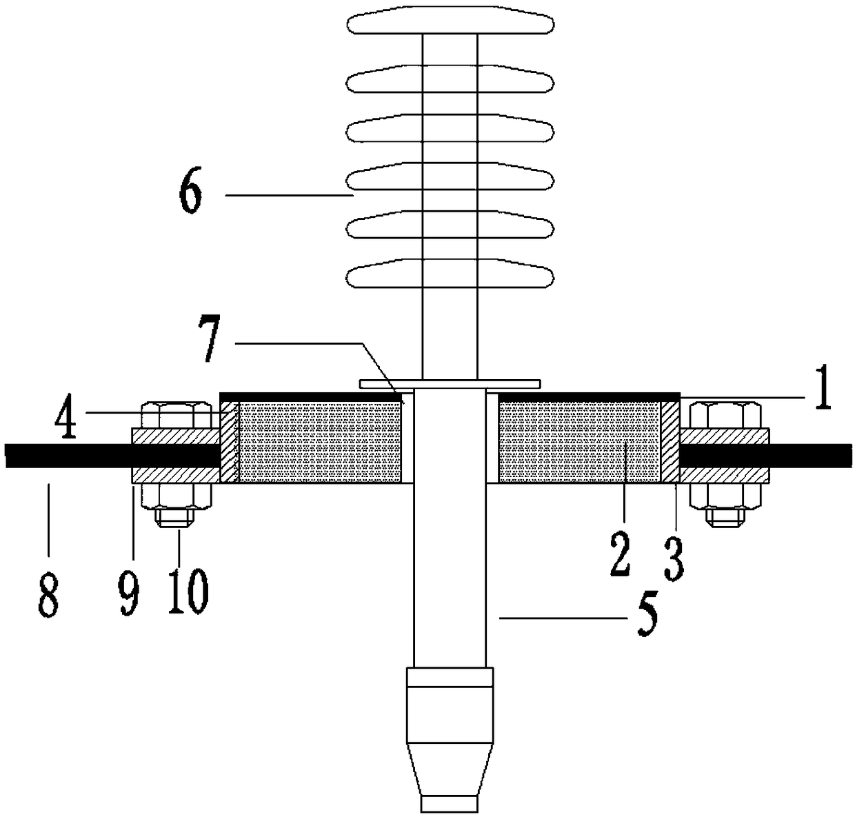
[0084] When the thickness of the constrained damping plate in the constrained damping layer 1 is 5 mm, the thickness of the galvanized steel plate is 2 mm, and the thickness of the damping rubber is 1 mm; The thickness of the sound-absorbing material filled inside is 89 mm, and the thickness of the insulating and sound-insulating material filled in the sound-insulating layer 7 is 2 mm; the noise measurement results are as follows:

[0085]

Embodiment 2

[0087] When the thickness of the constrained damping plate in the constrained damping layer 1 is 5 mm, the thickness of the galvanized steel plate is 1 mm, and the thickness of the damping rubber is 3 mm; The thickness of the sound-absorbing material filled inside is 90 mm, and the thickness of the insulating and sound-insulating material filled in the sound-insulating layer 7 is 2 mm; the noise measurement results are as follows:

[0088]

Embodiment 3

[0090] When the thickness of the constrained damping plate in the constrained damping layer 1 is 5 mm, the thickness of the galvanized steel plate is 1 mm, and the thickness of the damping rubber is 3 mm; The thickness of the sound-absorbing material filled inside is 30 mm, and the thickness of the insulating and sound-insulating material filled in the sound-insulating layer 7 is 2 mm; the noise measurement results are as follows:

[0091]


PUM

PropertyMeasurementUnit
Thicknessaaaaaaaaaa
Thicknessaaaaaaaaaa
Thicknessaaaaaaaaaa

Abstract

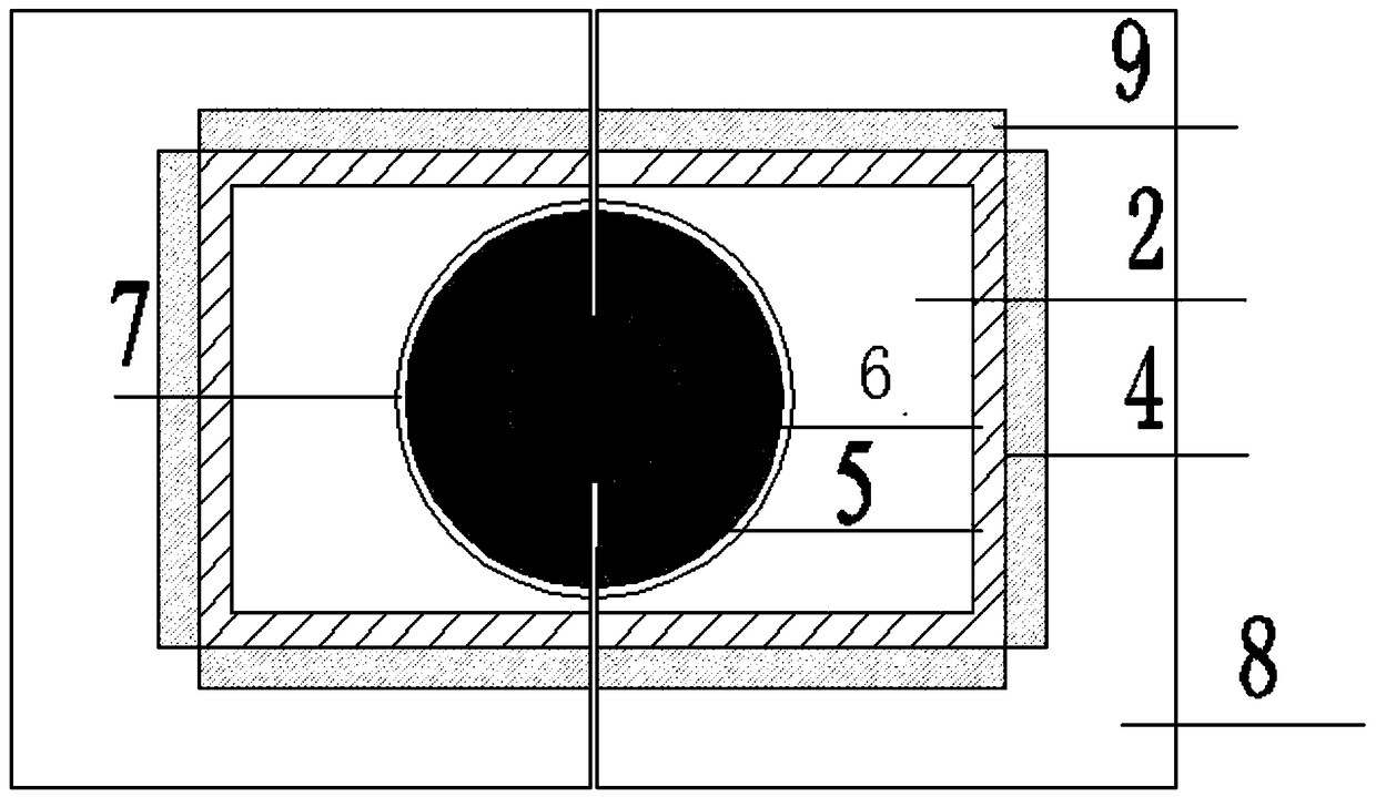
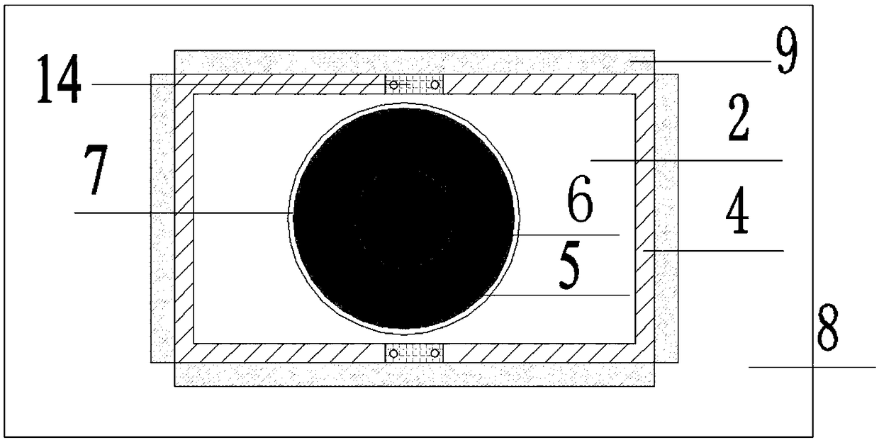
An acoustic insulation device of a transformer is provided. The acoustic insulation device is penetrated by an elevated seat of the transformer. The acoustic insulation device comprises a support frame, a restraining damping layer, a bearing layer and a sound absorbing layer. The constrained damping layer (1) and the load bearing layer (3) are respectively fixed on the top end and the bottom end of the support frame (4); The sound absorbing layer (2) is arranged between the constraint damping layer (1) and the bearing layer (3). The sound insulation device provided by the invention realizes good acoustic sealing to the transformer, and improves the sound insulation and noise reduction effect of the sound insulation cover at the position of the inlet and outlet lines. After the sound insulation device is applied, the noise value in the 2m area near the inlet and outlet lines is reduced by about 10dB (A) at most.

Description

technical field [0001] The invention relates to the field of noise control, in particular to a sound insulation device for a line outlet of a transformer sound insulation cover. Background technique [0002] In recent years, the noise problem of substations has gradually attracted public attention. In order to solve noise complaints and disputes, the power grid has vigorously promoted noise control. For outdoor substations, noise reduction measures such as "sound barrier" and "sound insulation cover" are mainly adopted. In addition to the sound insulation performance of the material itself, the sound insulation of the sound insulation cover also depends on the sealing degree of the sound insulation cover. This is because the sound energy density in the sound insulation enclosure is very high, and very small openings or gaps on the sound insulation enclosure can emit a lot of noise. Studies have shown that as long as 1% of the total area of ​​the sound insulation cover is op...

Claims


Application Information

Patent Timeline
IPC IPC(8): H01F27/33
CPCH01F27/33
Inventor 田一陈益坪聂京凯韩钰陈新金文德孔晓峰王斌李靖金晓峰张嵩阳王广周吕中宾
Owner GLOBAL ENERGY INTERCONNECTION RES INST CO LTD
Learn More