Circuit for detecting voltage changing rate of two ends of thyristor

A technology of voltage change rate and detection circuit, which is applied in the direction of change rate measurement, etc., can solve the problems of increasing the capacity of the resistance-capacitance absorption circuit, limited ability to suppress dv/dt, and increasing the overall loss of thyristor devices, etc., achieving a simple and reliable principle and fewer devices Effect

Active Publication Date: 2018-12-25
EXAMING & EXPERIMENTAL CENT OF ULTRAHIGH VOLTAGE POWER TRANSMISSION COMPANY CHINA SOUTHEN POWER GRID +1
View PDF15 Cites 0 Cited by
  • Summary
  • Abstract
  • Description
  • Claims
  • Application Information

AI Technical Summary

Problems solved by technology

[0003] In the application process of thyristor devices at home and abroad, it is usually adopted to reduce the dv / dt at both ends of the thyristor by connecting a resistance-capacity absorption circuit in parallel at both ends of the thyristor, but this will increase the capacity of the resistance-capacity absorption circuit, increase the overall loss of the thyristor device, and suppress dv / dt limited ability

Method used


Image

  • Circuit for detecting voltage changing rate of two ends of thyristor
  • Circuit for detecting voltage changing rate of two ends of thyristor

Examples


Embodiment Construction

[0014] In order to make the above objects, features and advantages of the present invention more comprehensible, the present invention will be further described in detail below in conjunction with the accompanying drawings and specific embodiments.

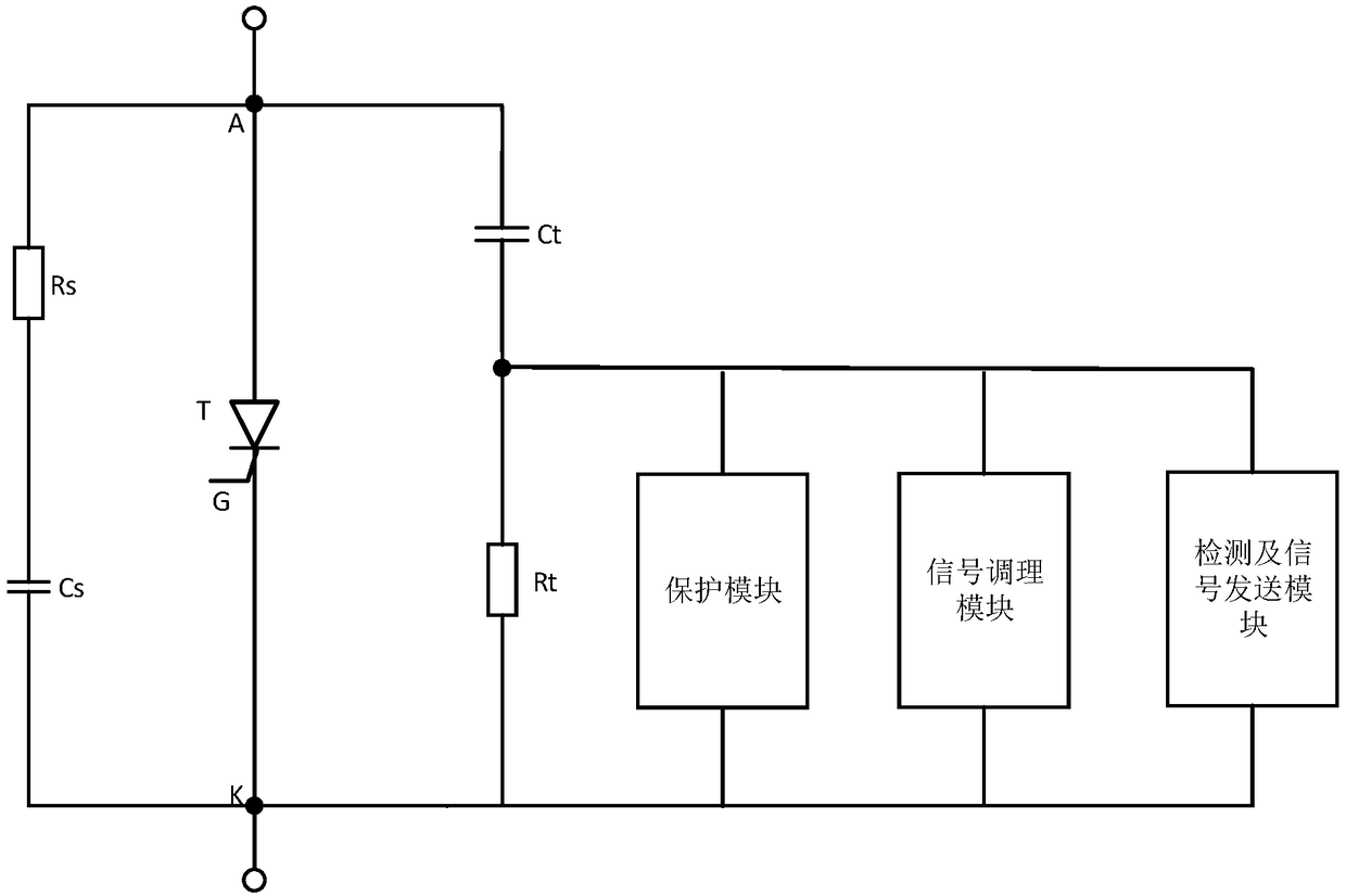
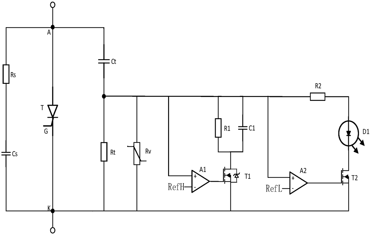
[0015] Such as figure 1 and figure 2 As shown, a detection circuit for the voltage change rate at both ends of a thyristor, including a capacitor Ct and a sampling resistor Rt connected in series across the two ends of the thyristor T, and a protection module, a signal conditioning module and a dv / dt detection module connected in parallel at both ends of the sampling resistor Rt and signal sending module.

[0016] The capacitor Ct and the sampling resistor Rt are connected in series across the two ends of the thyristor. The change of the voltage across the thyristor T makes the capacitor Ct generate a current proportional to the voltage change rate. The dv / dt of the voltage across the thyristor T can be obtained from the magnit...


PUM


Abstract

The invention discloses a circuit for detecting a voltage changing rate of two ends of a thyristor. The circuit comprises: a capacitor Ct connected in series and coupled across the two ends of a thyristor T; a sampling resistor Rt; a protection module, a signal conditioning module and a dv / dt detection and signal sending module which are all connected with the two ends of the sampling resistor Rtin parallel. Detection of dv / dt at the two ends of the thyristor T and output of a standard exceeding alarm signal are realized by the dv / dt detection and signal sending module; overvoltage protectionand large current bypass of the signal conditioning module and the dv / dt detection and signal sending module are realized by the protection module; and conditioning of the alarm signal output by thedv / dt detection and signal sending module are realized by the signal conditioning module, so that the pulse width of the alarm signal is larger than the minimum recognizable pulse width of the peripheral control device. According to the circuit for detecting a voltage changing rate of two ends of a thyristor, the detection circuit is simple in principle, rapid and reliable in action and can be used for protecting the thyristor from damage caused by excessive dv / dt.

Description

technical field [0001] The invention relates to the field of control and protection of electronic power devices, in particular to a detection circuit for the rate of change of voltage at both ends of a thyristor. Background technique [0002] When the thyristor is in the off state, when the rate of change of the voltage across the thyristor (dv / dt) is greater than a certain value, due to the existence of the gate junction capacitance, a large enough gate current may be generated, causing the thyristor to turn on by mistake, which in turn causes the device Work abnormally. During the turn-off period of the thyristor, due to the existence of the reverse recovery charge, the thyristor current will continue to flow in the reverse direction after being reduced to zero. This process is called the reverse recovery period of the thyristor device. If the thyristor on the thyristor during the reverse recovery period If the forward voltage rise rate is too high, the thyristor will be ...

Claims


Application Information

Patent Timeline
IPC IPC(8): G01R19/12
CPCG01R19/12
Inventor 王振安靖杨光源冯志畅刘坤任佳丽李左
Owner EXAMING & EXPERIMENTAL CENT OF ULTRAHIGH VOLTAGE POWER TRANSMISSION COMPANY CHINA SOUTHEN POWER GRID
Why Eureka
Try Eureka