
Experimental test method of buried displacing oil storage quantity of mixed gas flooding under high temperature and high pressure

A high temperature and high pressure, mixed gas technology, applied in soil material testing, material inspection products and other directions, can solve the problems of accurate evaluation of insufficient gas storage volume, low experimental pressure, no experimental test method for oil displacement storage volume, etc., and achieves easy operation. , the principle is reliable, the effect of broad market prospects

Active Publication Date: 2018-09-04
SOUTHWEST PETROLEUM UNIV
View PDF8 Cites 20 Cited by
  • Summary
  • Abstract
  • Description
  • Claims
  • Application Information

AI Technical Summary

Problems solved by technology

However, the existing experimental test methods are mostly aimed at the pure component gas CO 2 In the study of storage capacity in formation water or crude oil, there is no experimental test method for oil displacement storage capacity of mixed gas under actual reservoir conditions; at the same time, although the microscopic visualization model can intuitively analyze the distribution characteristics of the gas flooding process, the experimental method of this method The pressure is far lower than the actual reservoir formation pressure, which is not enough for accurate evaluation of gas storage

Method used


Image

  • Experimental test method of buried displacing oil storage quantity of mixed gas flooding under high temperature and high pressure
  • Experimental test method of buried displacing oil storage quantity of mixed gas flooding under high temperature and high pressure
  • Experimental test method of buried displacing oil storage quantity of mixed gas flooding under high temperature and high pressure

Examples


Embodiment Construction

[0035] Further illustrate the present invention according to accompanying drawing and embodiment below.

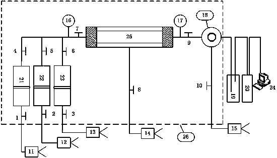
[0036] see figure 1 .

[0037] figure 1 It is a test device for long core gas flooding experiment, the device is mainly composed of formation water intermediate container 21, injected gas intermediate container 22, formation oil sample intermediate container 23, core holder 25, separator 19, gas meter 20, oven 26 composition, the left side of the core holder 25 is respectively connected to the formation water intermediate container 21 and the displacement pump A11, the injected gas intermediate container 22 and the displacement pump B12, the formation oil sample intermediate container 23 and the displacement pump C13, and the right side is respectively Connect the back pressure valve 18 and the back pressure pump 15, the separator 19 and the gas meter 20, the gas meter 20 is connected to the gas chromatograph 24; the rock core is housed in the core holder, and there are ...


PUM

PropertyMeasurementUnit
lengthaaaaaaaaaa

Abstract

The invention discloses an experimental test method of mixed gas flooding storage capacity under high temperature and high pressure. The experimental test method comprises the following steps: (1) preparing a crude oil fluid sample; (2) testing the single degassing oil ratio GORO; (3) testing injected gas composition and volume coefficients; (4) obtaining a reservoir plunger rock core sample in anactual gas reservoir; (5) putting a combined long rock core in a rock core clamper; (6) testing through connecting an experimental device, injecting a water sample in a formation water intermediate container into the rock core till formation water visiblely flows out of a separator; (7) injecting an oil sample in a formation oil sample intermediate container into the rock core till the water sample in the separator is not increased; (8) injecting a gas ample in an injected gas intermediate container into the rock core till no oil is produced at the outlet end of the rock core; (9) calculatingthe storage capacity of injected gas according to the GORi at different moments in the gas flooding process and the GOR0 of the prepared crude oil sample. The experimental test method disclosed by the invention is reliable in principle, simple and convenient to operate, strong in applicability and capable of determining the storage capacity and the distribution characteristics of each of injectedgas components in the rock core.

Description

technical field [0001] The invention relates to an experimental test method for the storage capacity of mixed gas flooding under high temperature and high pressure conditions in the field of oil and gas exploration and development. Background technique [0002] Oil flooding of industrial tail gas reinjection reservoirs is an important technical means to reduce harmful gas emissions at home and abroad. On the one hand, it can not only protect the environment, but also improve oil recovery. Generally speaking, industrial tail gas is a multi-component mixed gas, the main components of which include nitrogen (N 2 ), carbon dioxide (CO 2 ), carbon disulfide (CS 2 ), hydrogen sulfide (H 2 S), carbon monoxide (CO), etc. From the perspective of environmental protection, technicians are mainly concerned about carbon dioxide (CO2) in the process of industrial tail gas reinjection 2 ), hydrogen sulfide (H 2 S) and carbon monoxide (CO) stored in the reservoir and the distribution ...

Claims


Application Information

Patent Timeline
Patent Type & Authority Applications(China)
IPC IPC(8): G01N33/24
CPCG01N33/24
Inventor 汪周华王启贵李欣迎郭平杨龙杜建芬周伟张烈辉胡义升刘煌景明强
Owner SOUTHWEST PETROLEUM UNIV
Learn More