Confocal Displacement Sensor

A displacement sensor and confocal technology, applied in instruments, measuring devices, optical devices, etc., can solve problems such as difficult to identify the normal operation of control devices, achieve the effect of improving workability and preventing complicated structures

Active Publication Date: 2022-01-11
KEYENCE
View PDF9 Cites 0 Cited by
  • Summary
  • Abstract
  • Description
  • Claims
  • Application Information

AI Technical Summary

Problems solved by technology

[0007] In conventional confocal displacement sensors, it is also difficult to recognize whether the control device is operating normally near the installation position of the head unit

Method used


Image

  • Confocal Displacement Sensor
  • Confocal Displacement Sensor
  • Confocal Displacement Sensor

Examples


Embodiment Construction

[0040] Embodiments of the present invention will be described below with reference to the drawings. In this specification, for convenience, the direction of the optical axis of the head unit is described as the up-down direction. However, the posture and orientation during use of the head unit are not limited.

[0041] Confocal Displacement Sensor 1

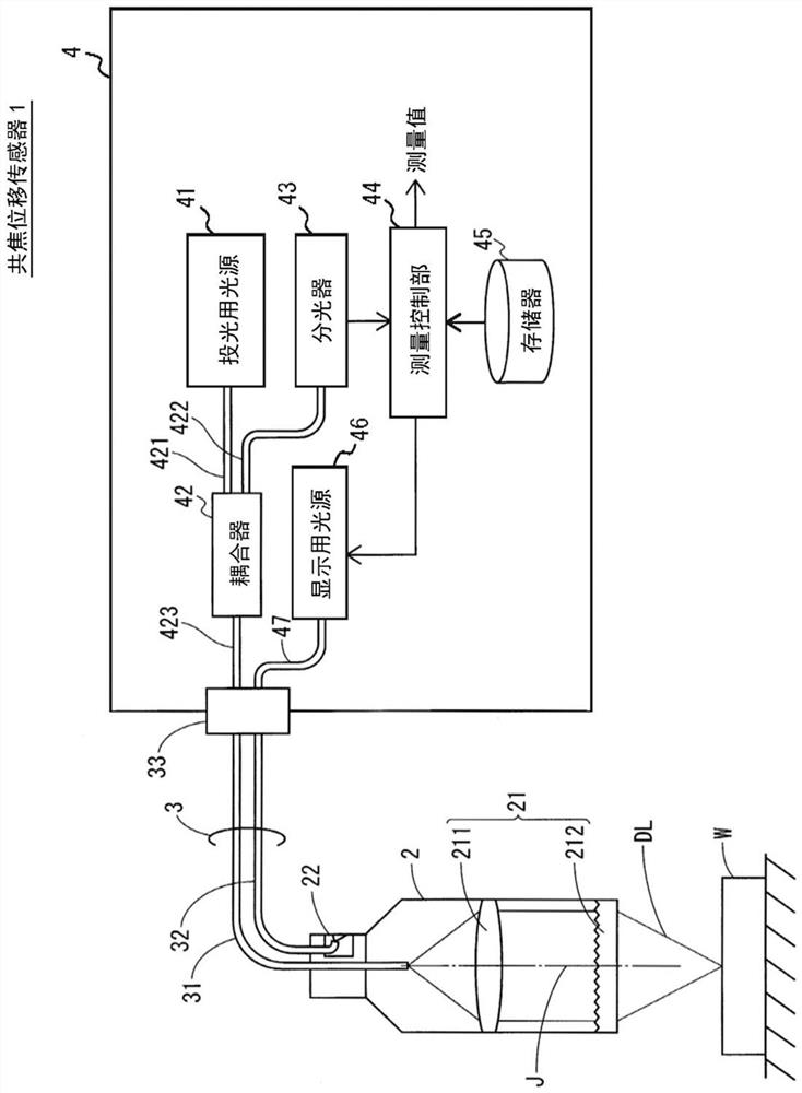
[0042] figure 1 is a system diagram showing a configuration example of the confocal displacement sensor 1 according to the embodiment of the present invention. The confocal displacement sensor 1 is an optical measurement device composed of a head unit 2 , an optical fiber cable 3 and a control device 4 . This optical measurement device receives reflected light from the measurement object W and measures the displacement of the measurement object W when the detection light DL is emitted from the head unit 2 .

[0043] The head unit 2 and the control device 4 are connected to each other via an optical fiber cable 3 . The optica...


PUM


Abstract

Provided is a confocal displacement sensor capable of improving workability when installing a head unit. The confocal displacement sensor includes: a head unit including a confocal optical system; a control device including a light source for projection; and an optical fiber cable including an optical fiber for transmitting light emitted from the light source for projection to the head unit. The head unit includes an optical member configured to cause axial chromatic aberration in detection light emitted via an end face of the optical fiber and to converge the detection light toward a measurement object. The control device includes: a spectroscope configured to disperse the spectrum of the detection light that is reflected when focused on the measurement object and passes through the end face of the optical fiber among the detection light irradiated to the measurement object via the optical member and generate a received light signal; and the measurement control A section configured to calculate a displacement of the measurement object based on the light-receiving signal. The head unit includes a display portion. The measurement control unit controls the display of the display unit using the operating state of the control device, the received light waveform, or the measured value of displacement.

Description

technical field [0001] The present invention relates to a confocal displacement sensor, and more particularly, to an improvement in a confocal displacement sensor that measures displacement of a measurement object using a confocal optical system. Background technique [0002] The confocal displacement sensor is an optical measurement device that uses the confocal principle (confocal principle) and the phenomenon of axial chromatic aberration (phenomenon of an axial chromatic aberration) to measure the displacement of the measurement object. The light received on the imaging surface of the image of the light source is formed as reflected light by stopping down, and the axial chromatic aberration phenomenon is a phenomenon in which color drift (color drift) in the direction of the optical axis occurs in the image of the light source . [0003] The confocal displacement sensor consists of a pin hole that emits light emitted from the light source as a point light source, an opt...

Claims


Application Information

Patent Timeline
Patent Type & Authority Patents(China)
IPC IPC(8): G01B11/02
CPCG01B11/02
Inventor 坂口富一武井英人
Owner KEYENCE
Why Eureka
Try Eureka