
Bent slot adjusting sliding frame

A sliding frame and curved groove technology, applied in the direction of machine/support, supporting machine, mechanical equipment, etc., can solve the problems of difficult maintenance, uneven thickness and uneven force in the later stage, and achieve enhanced stability and ease of use. The effect of counteracting damage

Inactive Publication Date: 2018-12-25
江苏三科海洋装备有限公司
View PDF5 Cites 0 Cited by
  • Summary
  • Abstract
  • Description
  • Claims
  • Application Information

AI Technical Summary

Problems solved by technology

[0002] At present, there are also machines in the market that can produce glass products by machinery. However, by analyzing the finished products, we can know that the produced glass products generally have problems such as uneven force, uneven thickness, and even weak points in the hand. , these problems can directly affect the vitality and service life of the product, and consumers can distinguish it well only by tapping on the surface of the glass product and listening to the sound. Although the production efficiency of these products is higher than that of the traditional production method, but However, it is limited by the quality of the product and cannot make a long-term breakthrough. Therefore, the inventor proposed an integrated machine that can achieve the effect of manual production through mechanical production, and all parts of the machine have been optimized. The combination of parts can complete the overall assembly of the integrated machine
[0003] The traditional adjustment carriage not only has extremely large defects and disadvantages in the setting, but also has an obvious force range in the structure, and the adjustment carriage in the traditional process has a short service life and is difficult to maintain later. Not conducive to the actual use of the carriage

Method used


Image

  • Bent slot adjusting sliding frame

Examples


Embodiment Construction

[0015] The present invention will be further described below in conjunction with specific embodiments.

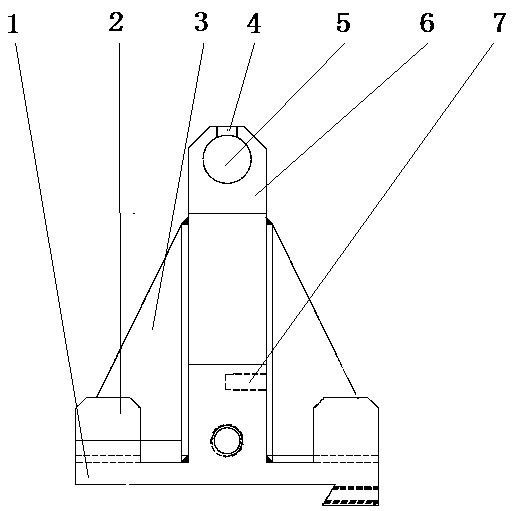
[0016] like figure 1 As shown, a curved groove adjustment carriage includes a base 1, a sliding beam 2, a reinforcing rib 3, a sliding groove 4, a positioning hole 5, a buffer beam 6 and an adjusting rod 7, and the curved groove adjusting carriage is a "mountain" as a whole. Font-shaped structure, the bottom end of the curved groove adjustment carriage is the base 1, and the plane where the base 1 is located is provided with a fixed base on one side of the bottom end, and the fixed base is tangent to one side edge of the base 1, and the base 1. A buffer beam 6 is provided at the straight line where the center line is located. The buffer beam 6 protrudes above the base 1 and is respectively connected with the shorter two sides of the base 1 through the sliding beam 2.

[0017] Between the sliding beam 2 and the buffer beam 6 is reinforced by the reinforcing rib 3, a buffer ...


PUM


Abstract

The invention discloses a bent slot adjusting sliding frame. The bent slot adjusting sliding frame comprises a base, sliding beams, reinforcing ribs, a sliding chute, a positioning hole, a buffer beamand an adjusting rod. The whole bent slot adjusting sliding frame is of a mountain-shaped structure; the base is arranged at the bottommost end of the bent slot adjusting sliding frame; a fixed baseis arranged on one side of the bottom end of a plane where the base is located; the fixed base is tangent to one side edge of the base; the buffer beam is arranged at a straight line where a center line of the base is located; the buffer beam extrudes from the upward side of the base and is connected with two relatively short side edges on two sides of the base through the sliding beams; the sliding beams and the buffer beam are reinforced through the reinforcing ribs; and the positioning hole is formed in a 1 / 3 position at the top end of the buffer beam. The bent slot adjusting sliding framehas certain adjusting adaptability for structures of bent slots, is capable of better carrying out adjustment, effectively strengthening the device stability and using convenience and better counteracting damages from external pressure and vibration to machines, and is suitable for the industry of glass product production.

Description

technical field [0001] The invention belongs to the technical field of automatic production, and more particularly relates to a curved groove adjusting carriage. Background technique [0002] At present, there are also machines on the market that can produce glass products mechanically, but by comparing the finished products and analyzing them, we can know that the output glass products generally have problems such as uneven force, uneven thickness, and even weak points in the hand. , these problems can directly affect the vitality and service life of products, and consumers can distinguish them well by tapping on the surface of glass products. Although the production efficiency of these products is higher than that of traditional methods, but However, it is limited by product quality and cannot make long-term breakthroughs. Therefore, the inventor proposes an integrated machine that can achieve manual production through mechanical production, and all parts of the machine ar...

Claims


Application Information

Patent Timeline
IPC IPC(8): F16M11/20
CPCF16M11/20
Inventor 钱海平彭琴
Owner 江苏三科海洋装备有限公司
Learn More