
Vibrating punching machine with returned oil cooling structure

A vibrator and oil cooling technology, applied in basic structure engineering, soil protection, construction, etc., can solve the problems of maintenance personnel burns, waste of replacement time, frequent replacement, etc., and achieve the effect of reducing the cost of use and improving production efficiency

Pending Publication Date: 2018-12-25
江阴市军炫智能装备有限公司
View PDF1 Cites 0 Cited by
  • Summary
  • Abstract
  • Description
  • Claims
  • Application Information

AI Technical Summary

Problems solved by technology

[0004] First, the heavy load resistance of the bearing is gradually weakened, and the fatigue life of the bearing is greatly reduced;
[0005] Second, bearings are often damaged and replaced frequently, which wastes unnecessary replacement time and greatly affects production efficiency;
[0006] Third, when shutting down for maintenance, unscrew the oil drain plug, high temperature and high pressure lubricating fluid will rush out of the cylinder, which may cause burns to maintenance personnel

Method used


Image

  • Vibrating punching machine with returned oil cooling structure
  • Vibrating punching machine with returned oil cooling structure
  • Vibrating punching machine with returned oil cooling structure

Examples


Embodiment 1

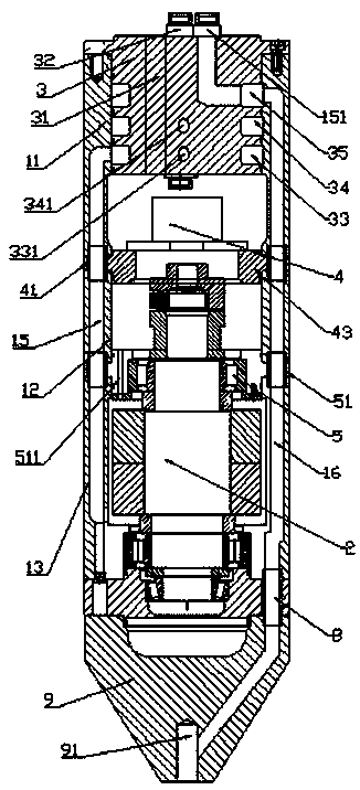
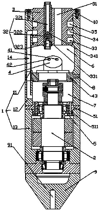
[0032] Such as figure 1 and figure 2 As shown, the vibrator with the oil return cooling structure of Embodiment 1 includes a vibrator cylinder 1, a vibrator main shaft 2 installed in the vibrator cylinder 1 through a bearing 5 and a vibrator embedded in the vibrator cylinder 1. The multi-port connection plate 3 in the vibrating cylinder 1 includes a motor shield 11, a connecting flange 12 and a cylinder 13 which are screwed in turn by screws 10, and the motor shield 11 is connected to the connecting flange 12 through a motor base 43, The connecting flange 12 is connected with the cylinder body 13 through the bearing seat 51;

[0033] The inner cavity of the vibrating cylinder 1 is divided into the first cavity 6 and the second cavity 7 by the bearing seat, the hydraulic motor 4 is arranged in the first cavity 6, the oil inlet 41 and the oil outlet 42 of the hydraulic motor 4 The system oil inlet connection 31 and the system oil return connection 32 are respectively connecte...

Embodiment 2

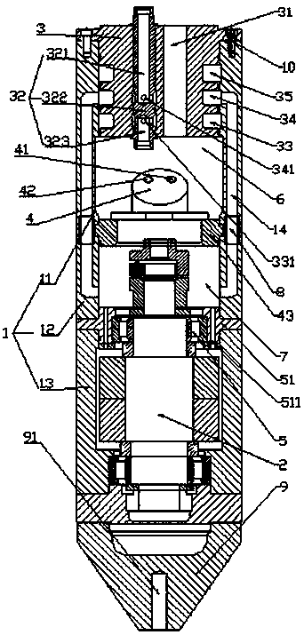
[0038] Such as image 3 As shown, the difference between Embodiment 2 and Embodiment 1 is that Embodiment 2 is provided with two system oil return channels.

[0039]Specifically, the number of motor oil return passages and / or the number of system oil return passages and / or the number of high pressure medium passages can also be set in multiples.


PUM


Abstract

The invention discloses a vibrating punching machine with a returned oil cooling structure. The vibrating punching machine comprises a vibrating punching barrel body, a vibrating punching main shaft,a hydraulic motor and a multi-port receiving disc, wherein the inner cavity of the vibrating punching barrel body is divided into a first cavity and a second cavity by a bearing base; an oil inlet andan oil outlet of the hydraulic motor separately communicate with an oil tank through a system oil inlet connecting tube and a system oil return connecting tube; the system oil return connecting tubecomprises a system oil return part, a blocking part and a motor oil return part; the blocking part is positioned between the system oil return part and the motor oil return part; a motor oil return runner which communicates with the motor oil return part, and a system oil return runner which communicates with the system oil return part are arranged on the side wall of the vibrating punching barrelbody; an outlet of the motor oil return runner directly communicates with the second cavity; a through hole is formed in the bearing base; the through hole is used for enabling the first cavity to communicate with the second cavity; and an inlet of the system oil return runner directly communicates with the first cavity. A bearing group of the vibrating punching machine is long in service life and is low in replacing frequency; and production efficiency can be improved, and a safety coefficient can be increased while the vibrating punching machine is used to construct.

Description

technical field [0001] The invention relates to a device for constructing densified soft ground by a vibration method, in particular to a vibrator with an oil return cooling structure. Background technique [0002] The vibrating method, also known as the vibrating water flushing method, refers to a foundation reinforcement method developed on the principle that the sandy soil foundation can be compacted by adding water and vibrating. The vibro-shock method is a foundation reinforcement treatment method to improve the bad foundation to meet the foundation requirements of buildings (structures). [0003] The vibrator is the main construction equipment in the vibro-construction. Existing vibrator, such as a vibrator disclosed in CN 201730088 U, includes a polarization axis, a vibrator head, a motor, a main bearing, and a connecting flange. The surrounding wall of the punch shell is connected with an anti-twist guard plate, the front end of the vibrator shell is provided with ...

Claims


Application Information

Patent Timeline
IPC IPC(8): E02D3/054
CPCE02D3/054
Inventor 许珊珊
Owner 江阴市军炫智能装备有限公司
Learn More