Three-phase synchronous machine and manufacturing method thereof
A technology of three-phase synchronization and manufacturing method, which is applied in the direction of electromechanical devices, prefabricated windings embedded in motors, electrical components, etc., can solve the problems of narrow freedom of coil selection and easily limited use.
- Summary
- Abstract
- Description
- Claims
- Application Information
AI Technical Summary
Problems solved by technology
Method used
Image

Examples
no. 1 approach >
[0077] (Overview of three-phase synchronous machine 100)
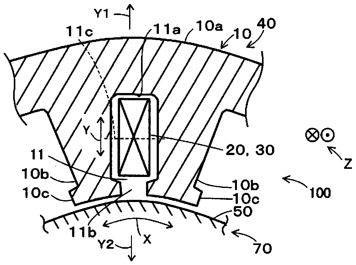
[0078] Such as figure 1 As shown, the three-phase synchronous machine 100 of this embodiment has a stator 40 and a mover 70. The stator 40 has a stator core 10 in which a plurality of slots 11 are formed, and a stator coil 30 including a plurality of unit coils 20. The mover 70 has a mover core 50 supported to be movable relative to the stator 40, and a plurality of pairs of mover magnetic poles 61 and 62 provided on the mover core 50.
[0079] In this embodiment, 60 slots 11 are formed in the stator core 10, and the stator coil 30 includes 12 each of three phases, and a total of 36 unit coils 20 are formed. In addition, in this embodiment, the mover core 50 has four pairs of mover magnetic poles 61 and 62. In this way, the three-phase synchronous machine 100 of the present embodiment is a three-phase synchronous machine with an 8-pole 60-slot structure (a three-phase synchronous machine with the basic structure of the mo...
no. 2 approach >
[0179] This embodiment is different from the first embodiment in the number of slots per pole per phase. In addition, this embodiment is different from the first embodiment in the arrangement of the half coil 23h. Hereinafter, the description will be focused on the differences from the first embodiment.
[0180] (The arrangement of the half coil 23h and a pair of coil lead-out portions 32f, 32s)
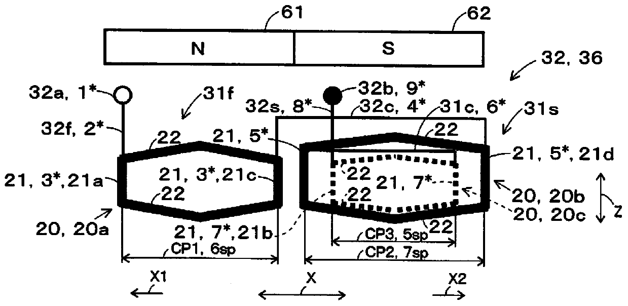
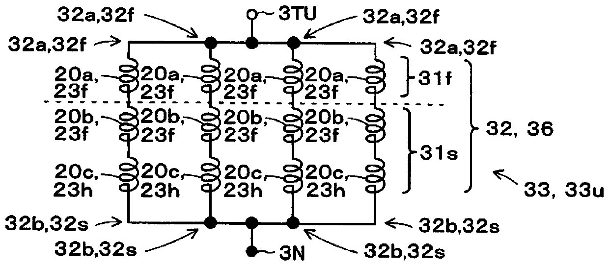
[0181] The three-phase synchronous machine 100 of this embodiment is a three-phase synchronous machine with an 8-pole 36-slot structure (a three-phase synchronous machine with the basic structure of the mover 70 having two poles and the stator 40 having 9 slots. ), the number of slots per phase per pole is 1.5. And like Picture 12 with Figure 13 As shown, in this embodiment, each pole pair coil 32 has one half coil 23h in the first pole coil 31f. The first pole coil 31f has one unit coil 20, and let this one unit coil 20 be the first unit coil 20a. The coil pitch between the pair of...
no. 3 approach >
[0205] This embodiment is different from the first embodiment in that the unit coils 36 of each phase of the three-phase phase coils 33 (U-phase coil 33u, V-phase coil 33v, and W-phase coil 33w) are pole coils 31. Hereinafter, the description will be focused on the differences from the first embodiment.
[0206] Such as Figure 16 As shown, a plurality of unit coils 20 (12 in each phase of the three phases, 36 in total) included in the stator coil 30 are arranged in accordance with multiple sets (four sets in this embodiment) of a pair of mover magnetic poles 61, 62 The mover magnetic poles of the same polarity (in this figure, the mover magnetic pole 61 of the N pole) face each other, and the slot units facing the pair of mover magnetic poles 61 and 62 are collected. Since the three-phase synchronous machine 100 of this embodiment is a three-phase synchronous machine with an 8-pole 60-slot structure, a plurality of unit coils 20 (three for each phase) are collected in units of 1...
PUM
 Abstract
Description
Claims
Application Information
 - R&D
- Intellectual Property
- Life Sciences
- Materials
- Tech Scout
- Unparalleled Data Quality
- Higher Quality Content
- 60% Fewer Hallucinations
Browse by: Latest US Patents, China's latest patents, Technical Efficacy Thesaurus, Application Domain, Technology Topic, Popular Technical Reports.
© 2025 PatSnap. All rights reserved.Legal|Privacy policy|Modern Slavery Act Transparency Statement|Sitemap|About US| Contact US: help@patsnap.com