
Panel filter with molded frame and integral seal

A filter and molding technology, applied in the fields of dispersed particle filtration, chemical instruments and methods, separation methods, etc., can solve the problems of leakage paths, filter elements cannot be closely matched, etc., and achieve the effect of eliminating leakage paths.

Active Publication Date: 2022-03-15
PARKER HANNIFIN CORP
View PDF13 Cites 0 Cited by
  • Summary
  • Abstract
  • Description
  • Claims
  • Application Information

AI Technical Summary

Problems solved by technology

Second, leak paths can occur at the corners of the filter in areas where there is a gap between the frame panels on each side of the filter
Third, leak paths can occur if the filter and the filter housing into which the filter is installed do not geometrically match ideally
For example, if the filter mount becomes curled or twisted as a result of expansion or temperature fluctuations, the filter element may not fit snugly within the mount

Method used


Image

  • Panel filter with molded frame and integral seal
  • Panel filter with molded frame and integral seal
  • Panel filter with molded frame and integral seal

Examples


Embodiment Construction

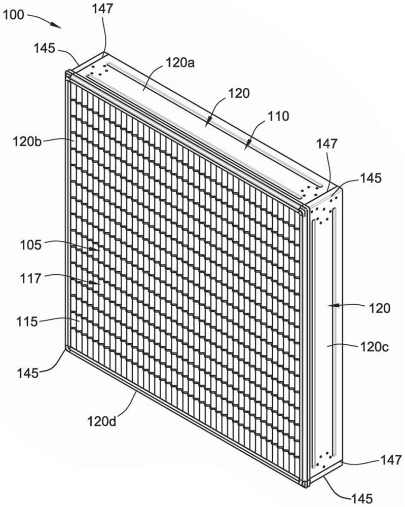
[0089] figure 1 A filter cartridge 100 is depicted according to an exemplary embodiment. The filter cartridge 100 includes a filter element 105 and a frame 110 .

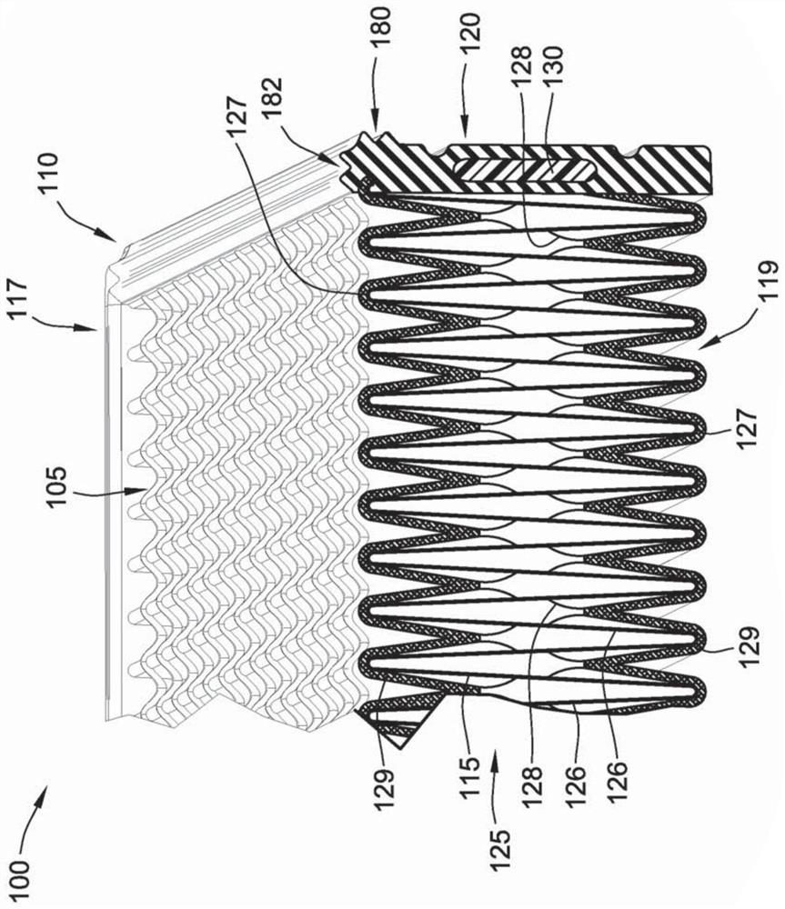
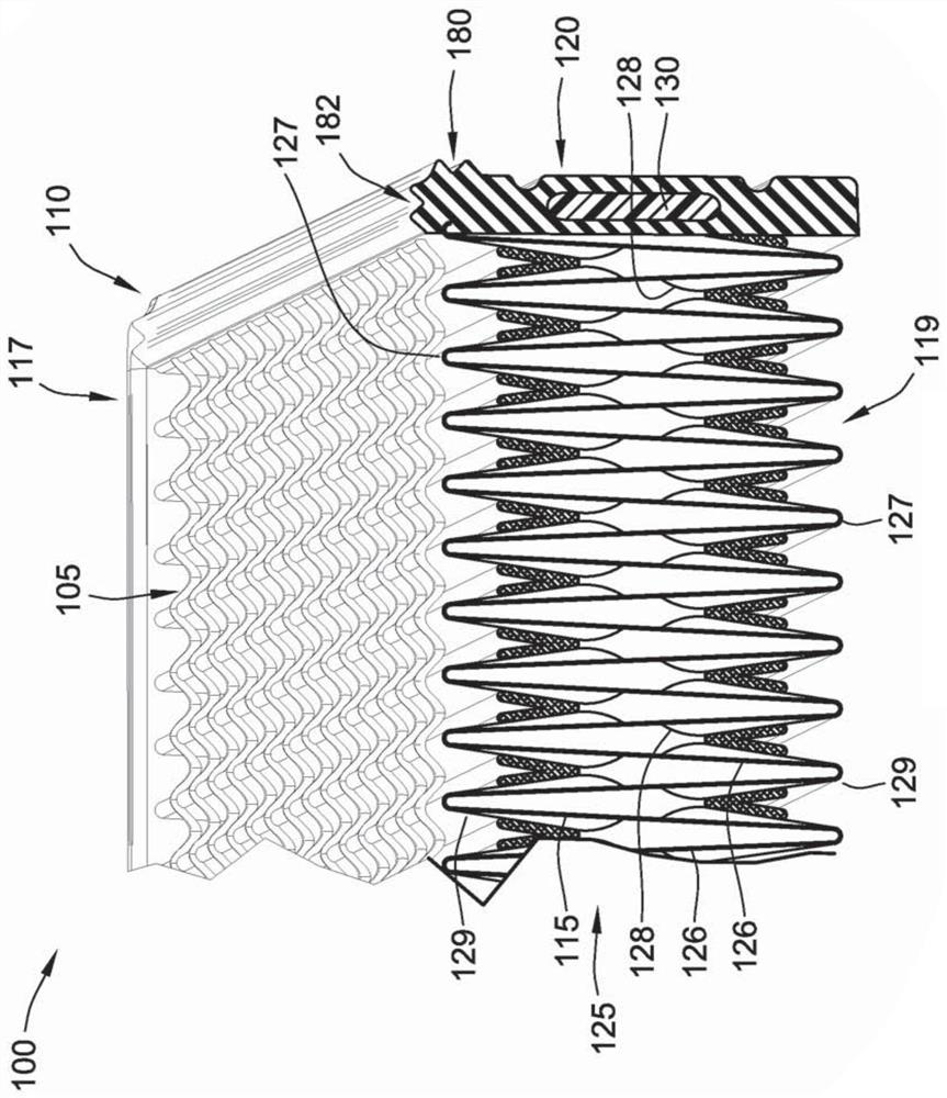
[0090] like Figure 2A As shown, filter element 105 includes filter media 115 extending between an outlet face 117 and an inlet face 119 . Although depicted as an outlet face 117 and an inlet face 119, those skilled in the art will recognize that the two faces are reversible, ie, unfiltered air can flow into either side so that filtered air can flow out the other. However, for purposes of reference, inlet and outlet faces are used herein to describe the various embodiments of the filter cartridges depicted in the figures. Furthermore, in a preferred embodiment, outlet face 119 has an axial seal feature (as will be discussed in more detail below) such that the force of incoming air entering filter element 105 causes the axial seal on rim 110 to press against Filter housing for enhanced sealing.

[0091] return ...


PUM


Abstract

A filter cartridge is provided. The filter cartridge includes a filter element including filter media, and the filter element extends between an inlet face and an outlet face. The filter element defines a perimeter around the filter media. The filter cartridge also includes a frame including a plurality of side panels, and the side panels are independently molded in place along the perimeter of the filter element. Adjacent members of the side panels are joined together along a plurality of mold interface seams, and the mold interface seams are spaced around the perimeter. The plurality of side panels fit into and seal the perimeter of the filter element such that fluid flow inside the frame is directed through the filter media for filtration from the inlet face to the outlet face.

Description

technical field [0001] The present invention relates generally to filters and, more particularly, to mold-in-place bezel features for panel air filters. Background technique [0002] When air containing particulate matter passes through the filter, the filter removes most of the particulate matter. To provide the most effective capture of particulate matter, leak paths should be prevented. [0003] The leak path through the filter can occur in various ways. First, leak paths may develop where the filter media is joined to the frame. If the filter media is not completely sealed to the frame panel, particulate matter may bypass the filter media in areas where the filter media is not sealed to the frame. Second, leak paths may occur at the corners of the filter in areas where there are gaps between the frame panels on each side of the filter. Third, leak paths can occur if the filter and the filter housing into which the filter is installed do not geometrically match ideall...

Claims


Application Information

Patent Timeline
Patent Type & Authority Patents(China)
IPC IPC(8): B01D46/52B01D46/42
CPCB01D46/0002B01D46/10B01D46/523B01D2271/025B01D46/0001B29C45/14B01D46/0005
Inventor D·R·哈斯L·A·克拉布特里H·E·范彻
Owner PARKER HANNIFIN CORP
Learn More