
Depth-of-field camera module

A camera module and depth-of-field technology, applied in the field of camera lenses, can solve the problems of low accuracy of the depth-of-field camera module

Active Publication Date: 2018-12-21
GOERTEK OPTICAL TECH CO LTD
View PDF4 Cites 10 Cited by
  • Summary
  • Abstract
  • Description
  • Claims
  • Application Information

AI Technical Summary

Problems solved by technology

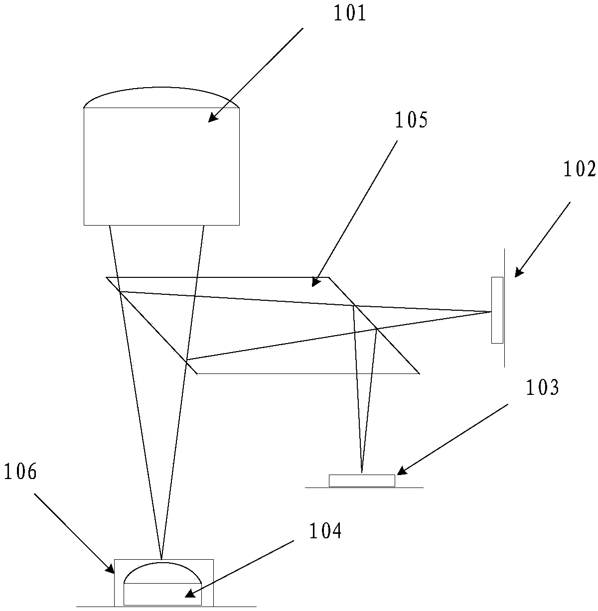
[0005] The embodiment of the present application provides a depth-of-field camera module, which can avoid the problem of low accuracy of the depth-of-field camera module due to the incompatibility of the field of view and distortion caused by the dual-camera structure

Method used


Image

  • Depth-of-field camera module
  • Depth-of-field camera module
  • Depth-of-field camera module

Examples


Embodiment Construction

[0042] In order to enable those skilled in the art to better understand the solutions of the present application, the following will clearly and completely describe the technical solutions in the embodiments of the present application in conjunction with the drawings in the embodiments of the present application.

[0043]In some processes described in the specification and claims of the present application and the description in the above-mentioned drawings, multiple operations appearing in a specific order are included, but it should be clearly understood that these operations may not be performed in the order in which they appear herein Execution or parallel execution, the serial numbers of the operations, such as 101, 102, etc., are only used to distinguish different operations, and the serial numbers themselves do not represent any execution order. Additionally, these processes can include more or fewer operations, and these operations can be performed sequentially or in pa...


PUM


Abstract

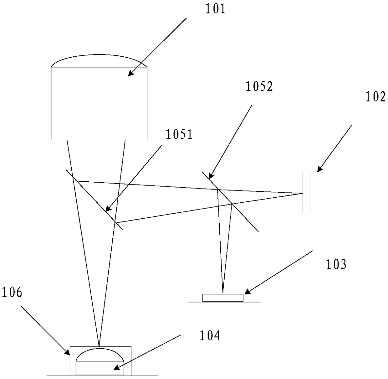
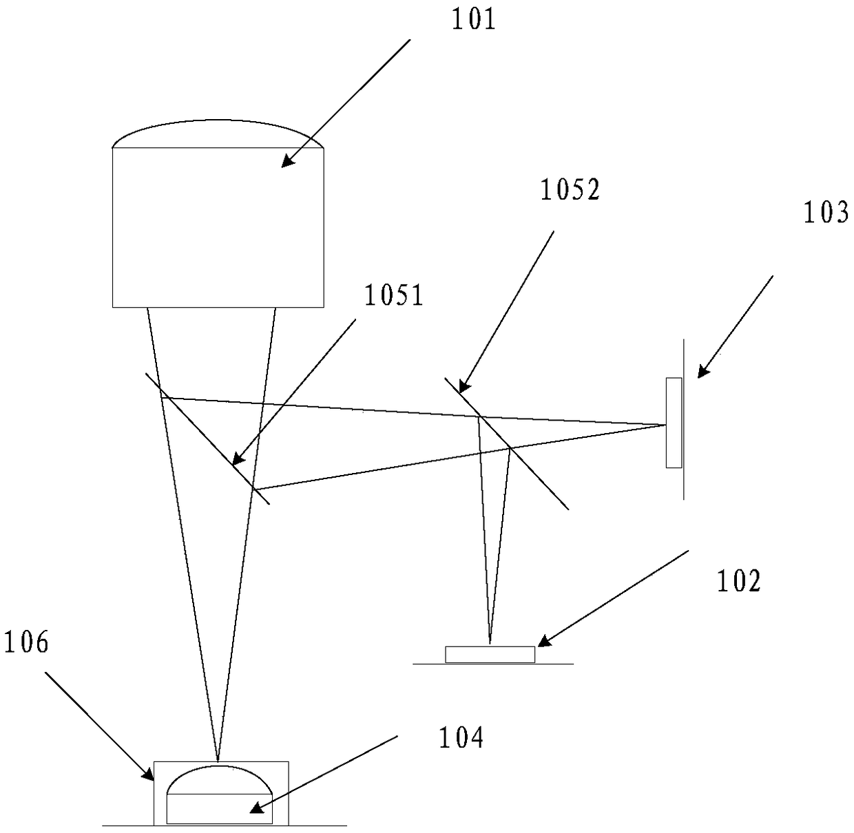
An embodiment of the present application provides a depth-of-field imaging module, comprising an imaging lens, a TOF sensor, an RGB sensor, a laser emitter, and an optical path conversion structure. The laser emitter is used to emit an infrared laser to that camera lens. The camera lens is used for transmitting infrared laser light to the target object. The reflected light beam reflected by the target object is received and transmitted to the optical path conversion structure. Reflected light includes infrared laser and ambient light reflected by the object. The optical path conversion structure is used for dividing at least part of the reflected light ray into a first target light ray and a second target light ray. A first target light is emitted to the TOF sensor and a second target light is emitted to the RGB sensor. The TOF sensor is used for obtaining depth information of a target object from an infrared laser in a first target light. The RGB sensor is configured to obtain RGB information of the target object from ambient light of the second target light. The present application can avoid the problem of low accuracy of the depth-of-field imaging module due to the use of a dualimaging structure.

Description

technical field [0001] The embodiments of the present application relate to the field of camera lens technology, and in particular to a depth-of-field camera module. Background technique [0002] With the rapid development of Internet of Things technology, users have higher and higher demands for intelligent interaction. The depth-of-field camera module is widely used in biometrics, VR (Virtual Reality, virtual Reality) / AR (Augmented Reality, Augmented Reality), autonomous driving, drones, 3D (three-dimensional) projection and other fields. [0003] The existing depth-of-field camera module adopts a dual-camera lens structure, one of which is an RGB (red, green, blue) camera equipped with an RGB sensor for generating an RGB image of a target object, and the other camera lens is a TOF (Time offlight, flight Time ranging method) The camera is equipped with a TOF sensor for collecting the depth information of the target object in three-dimensional space. In addition, a laser...

Claims


Application Information

Patent Timeline
IPC IPC(8): H04N5/225G03B17/17
CPCG03B17/17H04N23/50H04N23/56H04N23/55H04N23/54
Inventor 王岱杰
Owner GOERTEK OPTICAL TECH CO LTD
Learn More