
Quasi-resonant mode switching power supply controller and control method

A switching power supply, quasi-resonance technology, applied in the direction of control/regulation systems, instruments, electrical components, etc., can solve the problems of inapplicability, different operating frequencies, etc., and achieve the effects of improving EMI, eliminating audio noise, and enhancing universality

Active Publication Date: 2018-12-21
SUZHOU POWERON IC DESIGN
View PDF6 Cites 6 Cited by
  • Summary
  • Abstract
  • Description
  • Claims
  • Application Information

AI Technical Summary

Problems solved by technology

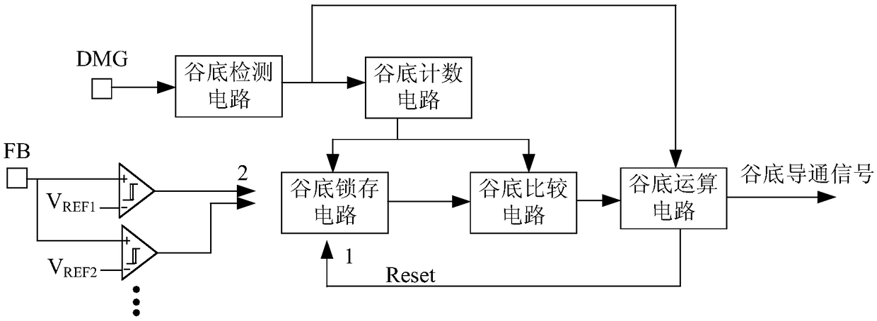
The disadvantage of this technical solution is that for systems with variable output voltage and output power levels, such as systems with fast charging schemes and USB PD schemes, different output voltages and output power levels are used for charging according to the battery level.
Between different output voltage gears, the same output voltage feedback signal or output current feedback signal corresponds to different load conditions, and its operating frequency will also be different. Therefore, conduction at a fixed valley bottom is not applicable to all output gears bit

Method used


Image

  • Quasi-resonant mode switching power supply controller and control method
  • Quasi-resonant mode switching power supply controller and control method
  • Quasi-resonant mode switching power supply controller and control method

Examples


Embodiment Construction

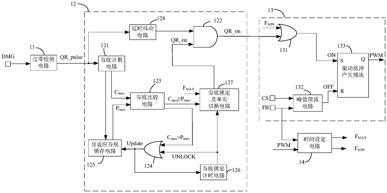
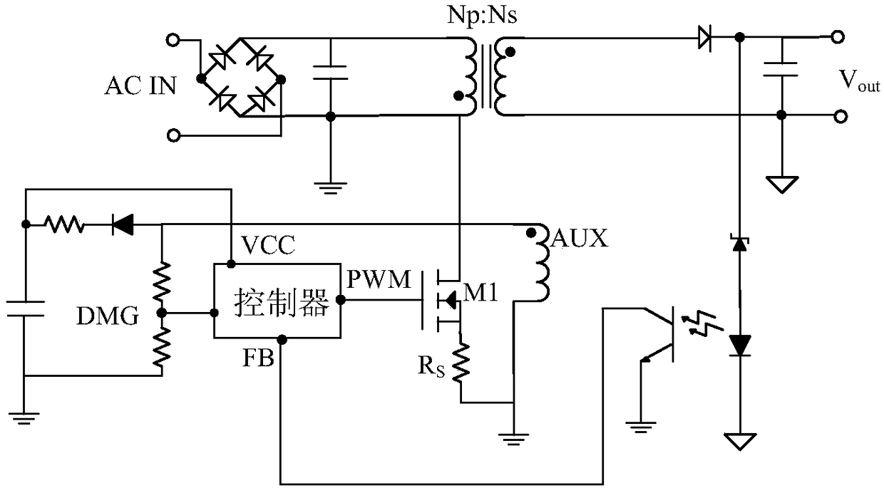
[0076] figure 2 It is a structural block diagram of a switching power supply controller in a quasi-resonant mode according to an implementation example of the present invention, which can be applied to image 3 In the quasi-resonant mode switching power supply shown according to an implementation example of the present invention, those skilled in the art can understand that the controller can be applied to other forms of converters, and is not limited to image 3 The specific implementation shown. For ease of understanding, here will combine figure 2 and image 3 Give a specific description.

[0077] A quasi-resonant mode switching power supply controller, comprising:

[0078] The zero-crossing detection circuit 11 is used to sample the zero-crossing point when the voltage at both ends of the power switch tube resonates through the degaussing pin DMG, and output a zero-crossing signal (Z_cross) after detecting the zero-crossing point.

[0079] The valley conduction logi...


PUM


Abstract

The invention discloses a quasi-resonant mode switching power supply controller and a control method thereof. The controller comprises a zero-crossing detection circuit which samples zero-crossing points and generates zero-crossing signals; a valley bottom conduction logic circuit which receives the zero-crossing signal and the maximum frequency signal, generates the valley bottom opening signal,and decides whether to select a new valley bottom for latching according to the preset judgment logic; a PWM logic control circuit which receives a valley bottom opening signal and a minimum frequencysignal, thereby controlling the PWM signal to be turned on, and controlling the PWM signal to be turned off according to the FB voltage signal and the CS voltage signal; and a time setting circuit which receives the PWM signal and the FB voltage signal, generates a maximum frequency signal and a minimum frequency signal, and thereby controlling the maximum frequency and the minimum frequency of the PWM operation. The invention not only can eliminate the audio noise caused by the continuous switching of adjacent valleys when the quasi-resonant mode operates, but also can improve the EMI, and has high use and popularization value.

Description

technical field [0001] The invention relates to a controller and a control method, in particular to a quasi-resonance mode switching power supply controller and a control method, belonging to the technical field of switching power supplies. Background technique [0002] Quasi-resonant mode is a kind of working mode of switching power supply. By controlling the power switch tube to turn on when the source-drain voltage reaches the minimum value, the switching loss can be controlled to the minimum, and the efficiency improvement is especially obvious for heavy load conditions. As the load lightens, both the excitation time and the demagnetization time are shortened, and the switching frequency will continue to increase when it is always turned on at the first valley. For EMI considerations, a maximum frequency is generally set and usually controlled below 150kHz. As the load is further reduced, the switching loss is usually further reduced by reducing the switching frequency....

Claims


Application Information

Patent Timeline
IPC IPC(8): H02M7/219H02M3/335H02M1/44
CPCH02M1/44H02M3/33523H02M7/219H02M1/0058Y02B70/10
Inventor 陶平秦浩高维李海松易扬波
Owner SUZHOU POWERON IC DESIGN
Learn More