An external self-locking structure of a connector

A self-locking structure and connector technology, which is applied to the parts of the connecting device, the device for connecting, connecting/disconnecting the connecting parts, etc. Hole pull fracture and other problems, to solve the problem of poor internal contact, save installation space, simple and convenient installation

Pending Publication Date: 2018-12-21
CHANGZHOU WUJIN FENGSHI COMM EQUIP
View PDF13 Cites 1 Cited by
  • Summary
  • Abstract
  • Description
  • Claims
  • Application Information

AI Technical Summary

Problems solved by technology

[0002] At present, the external connection structure of the N-type connector male and female connectors uses threaded connection when the male and female connectors are inter-matched. The conventional inter-system and inter-system N-type connector male and female connectors can meet the requirements of use, but in the airborne high-frequency vibration condition When used under the environment, when the vibration reaches a certain level, the thread may loosen, resulting in poor contact of the inner conductor of the male-female connector, and the microwave signal transmitted by the connector will have a transient phenomenon.
The current solution to this kind of problem is to punch three seal holes on the screw sleeve of the N-type male connector. After the connector thread is tightened, pass the steel wire through the seal hole and tie it in one direction Fixing on the chassis around the connector can solve certain problems. In the actual use process, there is a phenomenon that the magnitude of high-frequency vibration is too high, and the steel wire will break the lead seal hole on the screw sleeve, thereby making the structure invalid. The transmitted microwave The signal also produces a transient phenomenon

Method used


Image

  • An external self-locking structure of a connector

Examples


Embodiment Construction

[0021] The present invention is described in further detail below in conjunction with accompanying drawing:

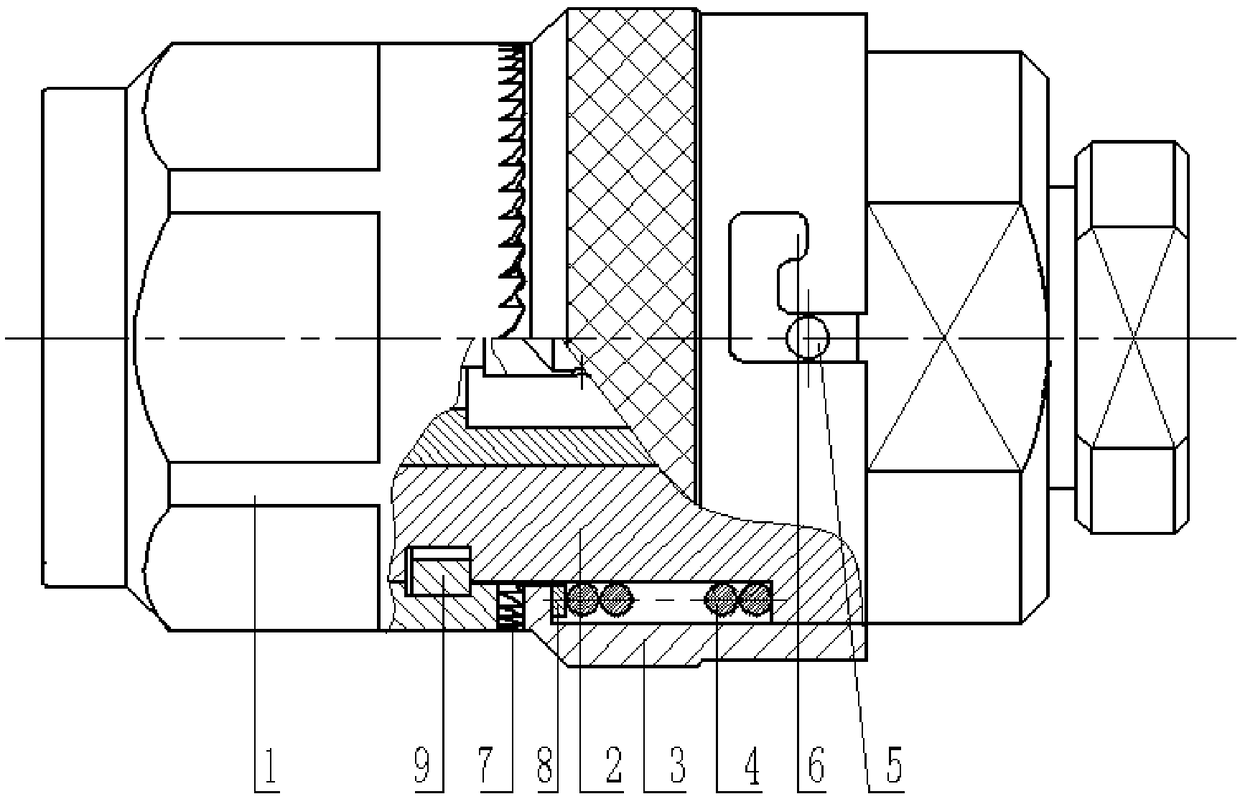
[0022] Such as figure 1 As shown, an external self-locking structure of a connector includes a screw sleeve 1, a housing 2 and a housing connecting sleeve 3, an inner conductor is provided inside the housing 2, one end of the housing 2 is connected to the screw sleeve 1, and the other end is used for Connect the cable to be connected, a spring groove is provided outside the circumference of one end of the housing 2 connected to the screw sleeve 1, a spring 4 is provided in the spring groove of the housing 2, and a collar 8 is provided at the outer end of the spring 4, and the spring 4 is connected by the collar. The spring 4 is limited on the housing 2 in the axial direction, and the housing connecting sleeve 3 is sleeved on the outside of the housing 2. A limiting platform is provided on the inner side of one end of the housing connecting sleeve 3, and one end of the ...


PUM


Abstract

An external self-locking structure of a connector is disclosed. A housing connecting sleeve with an engaging groove sleeves the outer side of the housing, and a hanging pin groove is arrange on the connecting sleeve of the case to match with the hanging pin on the case so as to limit the circumferential position of the connecting sleeve of the case, the engagement groove of the housing connectingsleeve and the engagement teeth on the screw sleeve are engaged and locked, pressure is applied by means of a spring, so as to ensure the meshing stability of the housing connecting sleeve and the screw sleeve, Screw down the threaded sleeve, After tightening, and then pushing the hanging pin on the connector housing into the hanging pin slot through the spring in the housing, The sawtooth are fully engaged with the locked design, ensuring good contact of the inner center contact, After the external connection is locked, the sawtooth meshes tightly in the high-frequency vibration process, andthe hanging pin does not spring back in the hanging pin groove. The device has the advantages of simple structure, simple and convenient installation, saves installation space, and solves the problemof instantaneous breakage of microwave signal caused by poor internal contact caused by loose screw thread in the high-frequency vibration process.

Description

technical field [0001] The invention relates to the mechanical field, in particular to an external self-locking structure of a connector. Background technique [0002] At present, the external connection structure of the N-type connector male and female connectors uses threaded connection when the male and female connectors are inter-matched. The conventional inter-system and inter-system N-type connector male and female connectors can meet the requirements of use, but in the airborne high-frequency vibration condition When used under the environment, when the vibration reaches a certain level, the thread may loosen, resulting in poor contact of the inner conductor of the male-female connector, and the microwave signal transmitted by the connector may be interrupted momentarily. The current solution to this kind of problem is to punch three seal holes on the screw sleeve of the N-type male connector. After the connector thread is tightened, pass the steel wire through the se...

Claims


Application Information

Patent Timeline
Patent Type & Authority Applications(China)
IPC IPC(8): H01R13/502H01R13/508H01R13/622
CPCH01R13/502H01R13/508H01R13/622
Inventor 王艳丽
Owner CHANGZHOU WUJIN FENGSHI COMM EQUIP
Why Eureka
Try Eureka