button

A technology for buttons and keycaps, applied in electrical components, electrical switches, circuits, etc., can solve the problems of occupying the internal space of the keys, injuring, and limiting the size of the notebook computer, reducing the overall height, reducing the height of the keycap, The effect of thin design

Active Publication Date: 2019-12-03
DARFON ELECTRONICS (SUZHOU) CO LTD +1
View PDF3 Cites 0 Cited by
  • Summary
  • Abstract
  • Description
  • Claims
  • Application Information

AI Technical Summary

Problems solved by technology

[0004] However, since the above-mentioned magnetic parts respectively arranged on the supporting device and the bottom plate will occupy the internal space of the key, the key still has a certain structural height. The keycaps on the body damage the display screen arranged on the upper cover, and there is often a gap between the upper cover and the lower case to accommodate the keycaps, which will limit the appearance and size design of the notebook computer, which is not conducive to the thinness of the notebook computer. design

Method used


Image

  • button
  • button
  • button

Examples


Embodiment Construction

[0036] The aforementioned and other technical contents, features and effects of the present invention will be clearly presented in the following detailed description of a preferred embodiment with reference to the drawings. The directional terms mentioned in the following embodiments, such as: up, down, left, right, front or back, etc., are only directions referring to the attached drawings. Accordingly, the directional terms are used to illustrate and not to limit the invention.

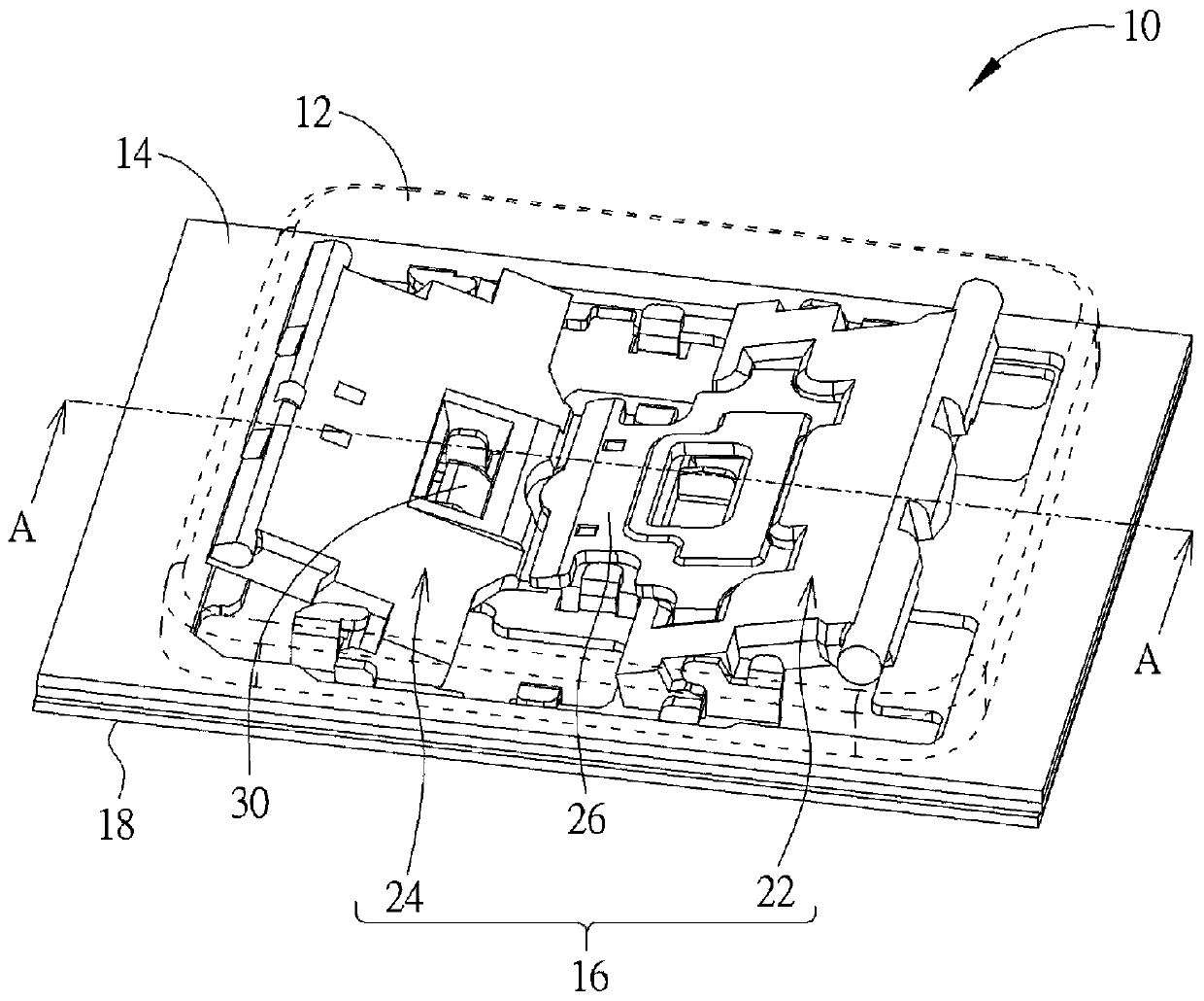
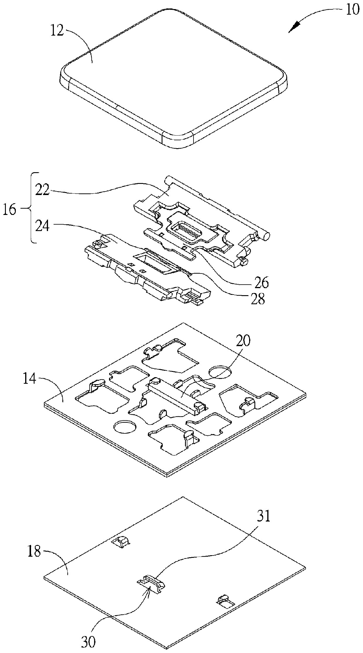
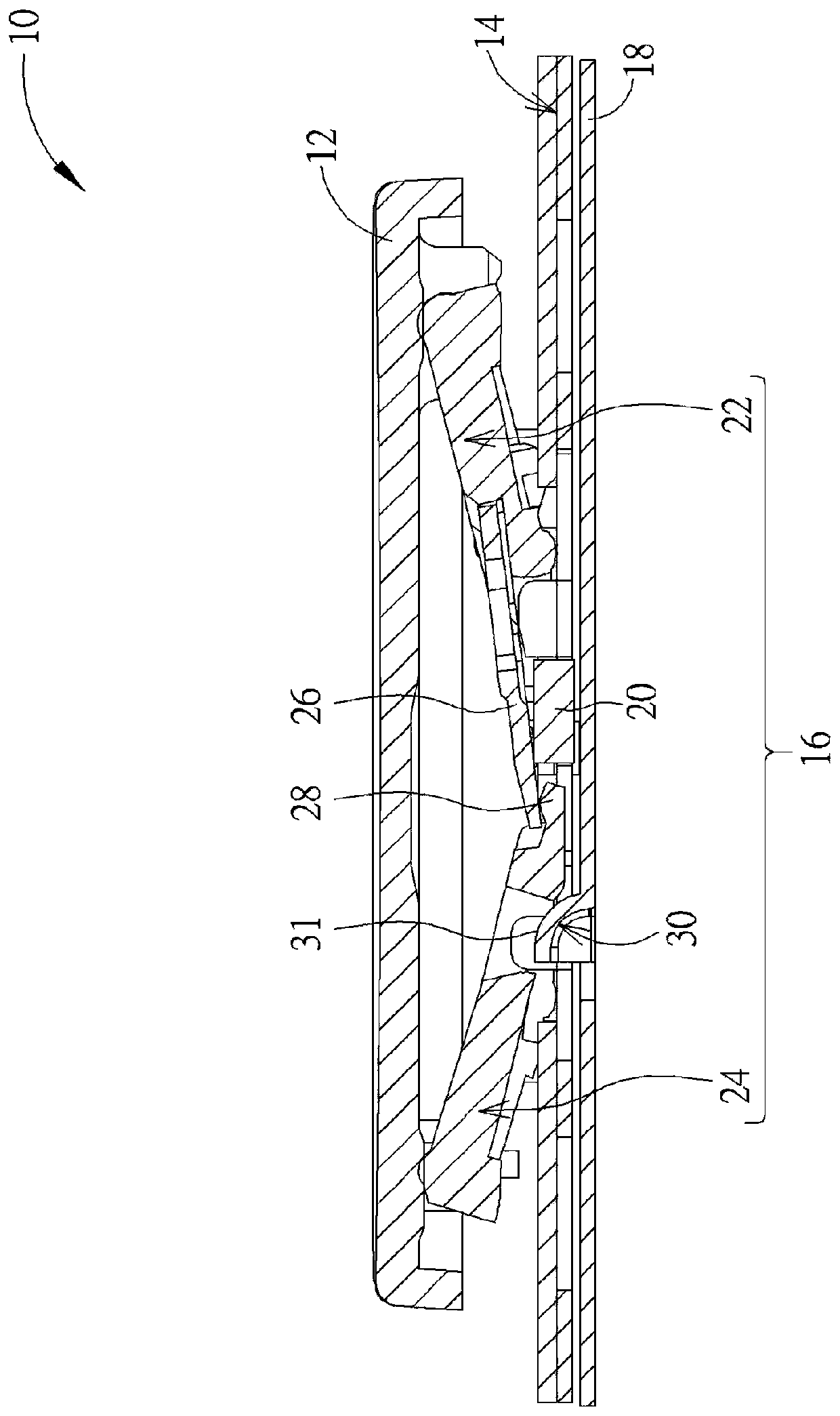
[0037] see figure 1 , figure 2 ,as well as image 3 , figure 1 It is a three-dimensional schematic diagram of the button 10 proposed according to an embodiment of the present invention, figure 2 for figure 1 Explosion diagram of button 10 in the middle, image 3 for figure 1 A schematic cross-sectional view of the middle button 10 along the section line A-A, wherein in order to clearly show the internal structure of the button 10, the keycap 12 is figure 1 Indicated by the dotted line in p...


PUM


Abstract

The invention relates to a key, comprising a key cap, an upper bottom plate with a first magnetic member, a support device and a lower bottom plate. The support device is arranged between the upper bottom plate and the key cap and comprises a first support member and a second support member pivotally connected with the key cap and the upper bottom plate so as to move the key cap up and down. The first support member has a second magnetic member corresponding to the first magnetic member, and the support portion extends from the second support member to the first support member to support underthe second magnetic member. A lower bottom plate is provided with a push-top plate member slidably disposed below that upper bottom plate to slide between a push-top position and a non-push-top position, the push-top plate member protrudes from the lower bottom plate toward the key cap and is formed by bending through the upper bottom plate. When the key cap is not pressed and the lower bottom plate slides to the pushing position, one of the first support member and the second support member is pushed laterally by the pushing top plate member to drive the second magnetic member away from thefirst magnetic member so as to move the key cap downward. Thus, the keyboard may be in a state in which the height of the key cap is lower to further reduce the overall height of the keyboard.

Description

technical field [0001] The present invention relates to a key, in particular to a key that uses a push plate of the lower bottom plate that can slide relative to the upper bottom plate to laterally push the supporting device to reduce the height of the key cap. Background technique [0002] As far as the current usage habits of notebook computers are concerned, the keyboard is one of the indispensable input devices for inputting characters, symbols or numbers. Recently, due to the thinning trend of the notebook computer, the keyboard used in the notebook computer also needs to be thinned. [0003] Generally, the traditional keyboard adopts a pressing design in which the assembly structure of the scissors foot support device and the elastic member is arranged between the keycap and the bottom plate, so that when the keycap is pressed by the user, the elastic member provides elastic restoring force to the keycap, so as to The driving keycap returns to the position before pres...

Claims


Application Information

Patent Timeline
Patent Type & Authority Patents(China)
IPC IPC(8): H01H13/705H01H13/7065
CPCH01H13/705H01H13/7065
Inventor 谢铭元叶亮达
Owner DARFON ELECTRONICS (SUZHOU) CO LTD
Why Eureka
Try Eureka