Loading system and method based on remote FPGA
A loading system and remote technology, applied in the direction of boot program, program control device, software engineering design, etc., can solve the problems of difficult operation and long overall time, and achieve the effect of saving maintenance cost and shortening maintenance time.
- Summary
- Abstract
- Description
- Claims
- Application Information
AI Technical Summary
Problems solved by technology
Method used
Image
Examples
Embodiment 1
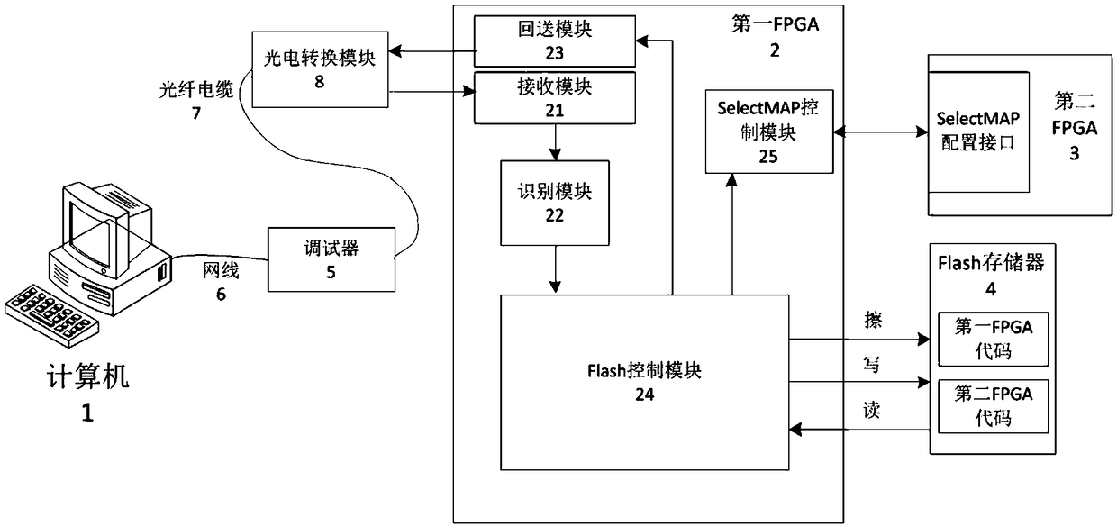
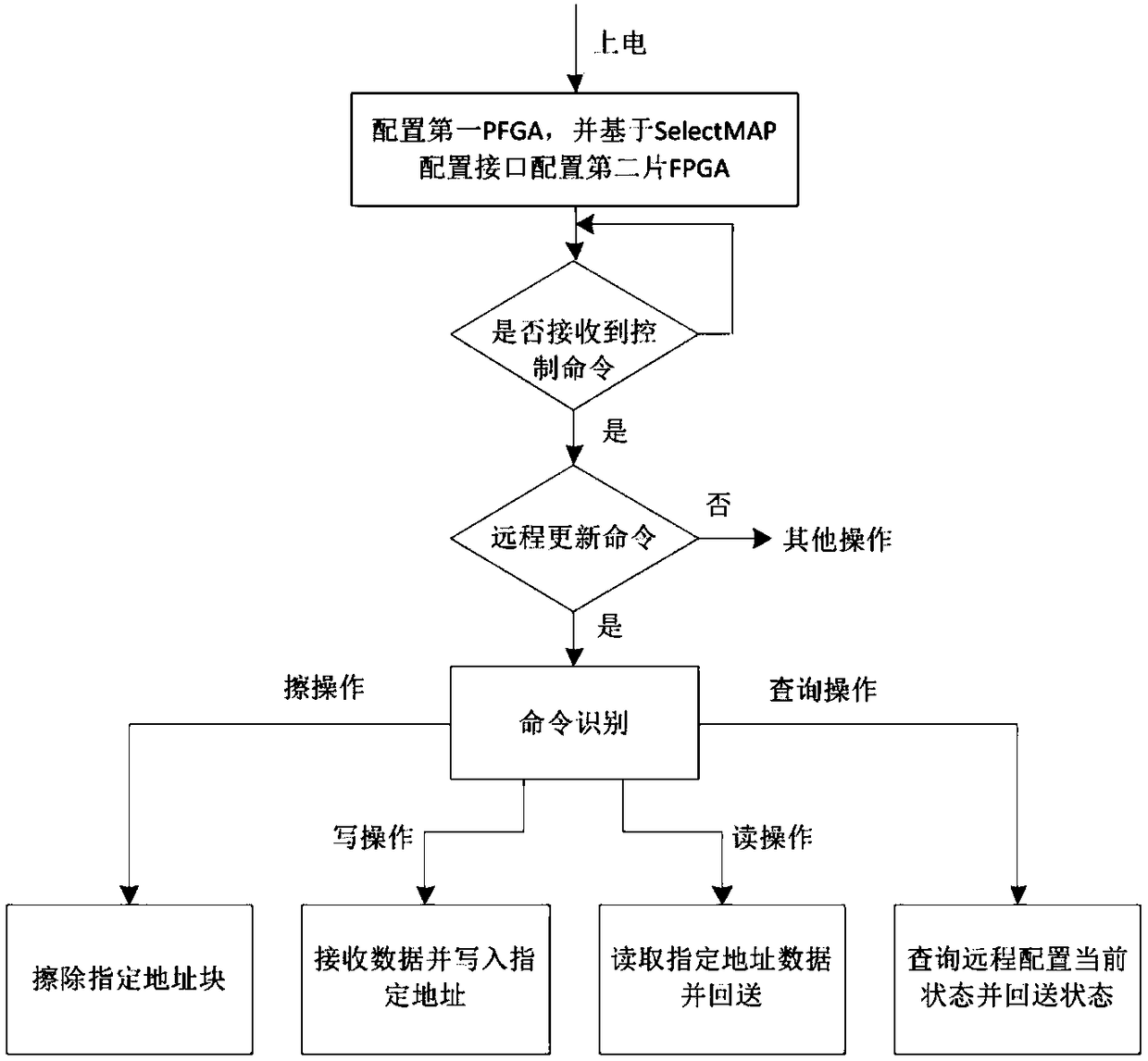
[0046] Such as figure 1 As shown, this example discloses a remote FPGA loading system, which includes: the first PFGA2 and Flash memory 4 applied in a remote complex environment; when the first PFGA2 is powered on and working, it will obtain the second A configuration code, using the first configuration code to load the first FPGA; after self-loading, obtain the second configuration code from the Flash memory 4, and load the configuration code into the corresponding second FPGA based on the SelectMAP configuration interface, Complete the initial configuration of the FPGA. In this embodiment, if the first PFGA2 receives an update instruction based on the optical fiber network, the second configuration code in the Flash memory 4 is updated; when the second configuration code updated in the Flash memory 4 needs to be applied to the FPGA, it needs Re-energize the first FPGA, re-acquire the updated first configuration code and the second configuration code from the Flash memory 4,...
Embodiment 2
[0054] Such as figure 1 As shown, a program loading system that uses optical fiber remote control and loads programmable logic device FPGA through SelectMAP. The system includes: computer 1, the first FPGA2, the second FPGA3, Flash memory 4, debugger 5, network cable 6, optical fiber cable 7 and photoelectric conversion module 8; wherein, the first FPGA2 also includes receiving module 21, analysis and identification module 22 , loopback module 23, Flash control module 24, SelectMAP control module 25; The second FPGA3 includes the SelectMAP configuration interface, and is configured as a slave mode; the data in the Flash memory 4 includes: the first FPGA code and the second FPGA code. The computer 1 is connected to the debugger 5 through the network cable 6, the debugger 5 is connected to the photoelectric conversion module 8 through the optical fiber cable 7, the photoelectric conversion module 8 is connected to the first FPGA2, and the first FPGA2 is connected to the Flash me...
PUM
 Abstract
Description
Claims
Application Information
 - R&D
- Intellectual Property
- Life Sciences
- Materials
- Tech Scout
- Unparalleled Data Quality
- Higher Quality Content
- 60% Fewer Hallucinations
Browse by: Latest US Patents, China's latest patents, Technical Efficacy Thesaurus, Application Domain, Technology Topic, Popular Technical Reports.
© 2025 PatSnap. All rights reserved.Legal|Privacy policy|Modern Slavery Act Transparency Statement|Sitemap|About US| Contact US: help@patsnap.com


