
A Method for Measuring the Vertical Section Deformation of Shipborne Large Radar Base

A measurement method and technology of the vertical section, which is applied in the field of deformation measurement of the vertical section of the shipboard large-scale radar base, can solve the problems that the equipment system occupies a large deck space, and the dedicated optical channel is difficult to guarantee, so as to improve the radar measurement accuracy and occupy a small space , The effect of convenient operation and implementation

Active Publication Date: 2020-05-19
中国卫星海上测控部
View PDF4 Cites 0 Cited by
  • Summary
  • Abstract
  • Description
  • Claims
  • Application Information

AI Technical Summary

Problems solved by technology

The current emerging camera deformation measurement method is a more convenient method, but still requires a dedicated optical channel, but it is much smaller than the traditional large steel pipe deformation measurement method
The above two types of methods have high precision and the equipment works stably, but the equipment system takes up a lot of space on the deck, and sometimes it is difficult to guarantee the dedicated optical channel

Method used


Image

  • A Method for Measuring the Vertical Section Deformation of Shipborne Large Radar Base
  • A Method for Measuring the Vertical Section Deformation of Shipborne Large Radar Base
  • A Method for Measuring the Vertical Section Deformation of Shipborne Large Radar Base

Examples


Embodiment Construction

[0049]The specific implementation manners of the present invention will be further described below in conjunction with the drawings and examples. The following examples are only used to illustrate the technical solution of the present invention more clearly, but not to limit the protection scope of the present invention.

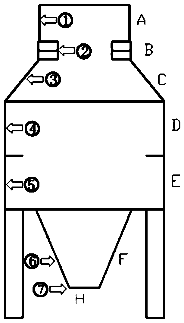
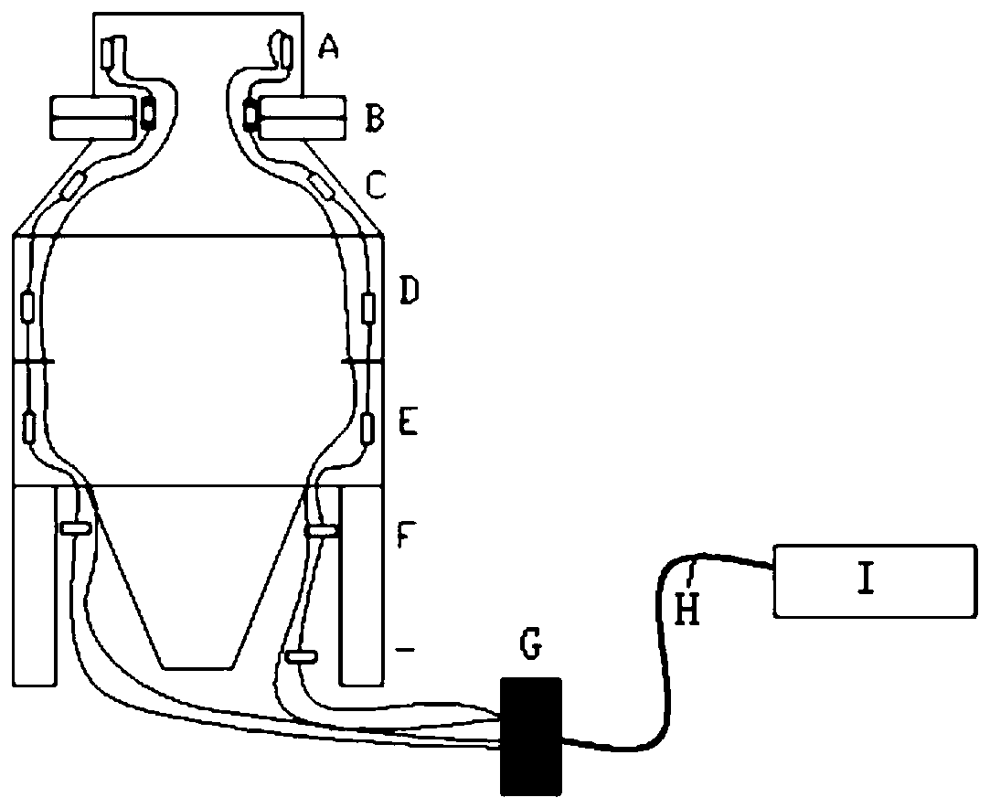
[0050] The invention relates to a method for measuring the deformation of the vertical section of a ship-borne large-scale radar base. The measurement method is to install the optical fiber Bragg grating sensor on the radar in sections along the port side, starboard side, bow side and stern side of the ship. For the inner wall of the barrel wall of the base, determine the deformation measurement and calculation method according to the installation plan, including the following measurement steps:

[0051] Step 1. Determine the installation position of the sensor: the optical fiber sensor used for deformation measurement should be installed in sections along t...


PUM


Abstract

The invention belongs to the technical field of spacecraft measurement and control, and discloses a method for measuring deformation of a vertical section of a shipborne large radar base. In view of the lack of available measurement methods for structural deformation in the vertical direction of current shipborne large-scale radar antenna bases, the method for measuring deformation of the verticalsection of the shipborne large radar base utilizes high-precision structural strain measurement capability of a fiber bragg grating sensor, and through an appropriate installation scheme design and acorresponding local strain variable and global deformation value calculation model, the measured value of the deformation of the radar base in the vertical direction is obtained. The method overcomesthe difficulty that a conventional optical deformation measurement method using a direct connection light path is difficult to implement due to the limited installation space inside the radar base. According to the method for measuring deformation of the vertical section of the shipborne large radar base, the fiber bragg grating sensor can be closely installed on the barrel wall of the radar basein an attaching mode, the space occupation is small, the deformation measurement precision is high, and the deformation of the radar base in the vertical direction can be obtained in real time at seadynamic conditions, so that the measurement accuracy of a shipborne radar can be improved.

Description

technical field [0001] The invention relates to the technical field of space vehicle measurement and control, in particular to a method for measuring deformation of a vertical section of a ship-borne large radar base. Background technique [0002] Due to its unique advantages of all-weather and all-weather applications, radio radar systems play an increasingly important role in space surveillance, target detection, especially in aerospace measurement and control. As one of the most important performance indicators, radar measurement accuracy has long been the focus of research and design by engineers and technicians. Due to the characteristics of platform movement, shipborne radar has more factors restricting the measurement accuracy than land-based radar. Especially due to the influence of ship motion, the shafting error and structural deformation of the radar base have the characteristics of dynamic changes, but due to technical reasons, there has been no suitable method ...

Claims


Application Information

Patent Timeline
Patent Type & Authority Patents(China)
IPC IPC(8): G01S7/40G01B11/16
CPCG01B11/165G01S7/40
Inventor 陈嘉鸿刘勇赵文华凌晓冬
Owner 中国卫星海上测控部
Learn More