
Current sensor testing device

A technology of current sensor and testing device, applied in the direction of measuring device, instrument, measuring electrical variable, etc., can solve the problems of inconvenient testing, no good fixing method, single testing device, etc., and achieve the effect of convenience and stability

Active Publication Date: 2018-12-21
ANHUI SHUORI PHOTOELECTRIC TECH
View PDF8 Cites 0 Cited by
  • Summary
  • Abstract
  • Description
  • Claims
  • Application Information

AI Technical Summary

Problems solved by technology

[0003] With the continuous development of current sensors, the scope of use of current sensors is also increasing, especially high-speed current sensors such as magnetic modulation and flux. However, the traditional current sensor test device is relatively simple, and there is no better fixing method. Extremely inconvenient when testing

Method used


Image

  • Current sensor testing device
  • Current sensor testing device
  • Current sensor testing device

Examples


Embodiment Construction

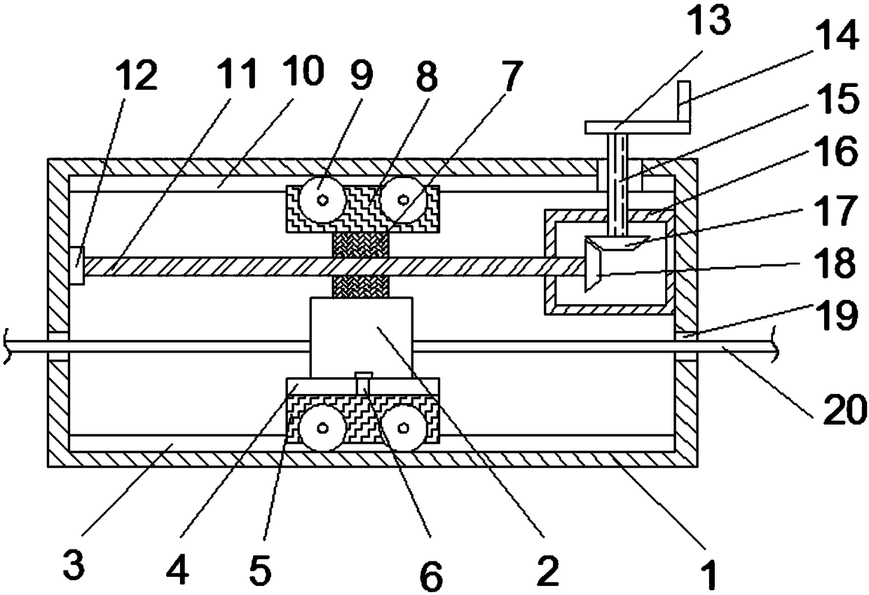
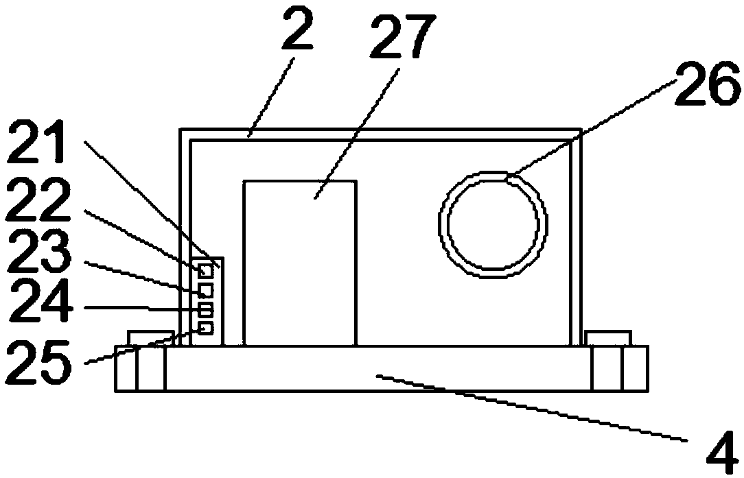
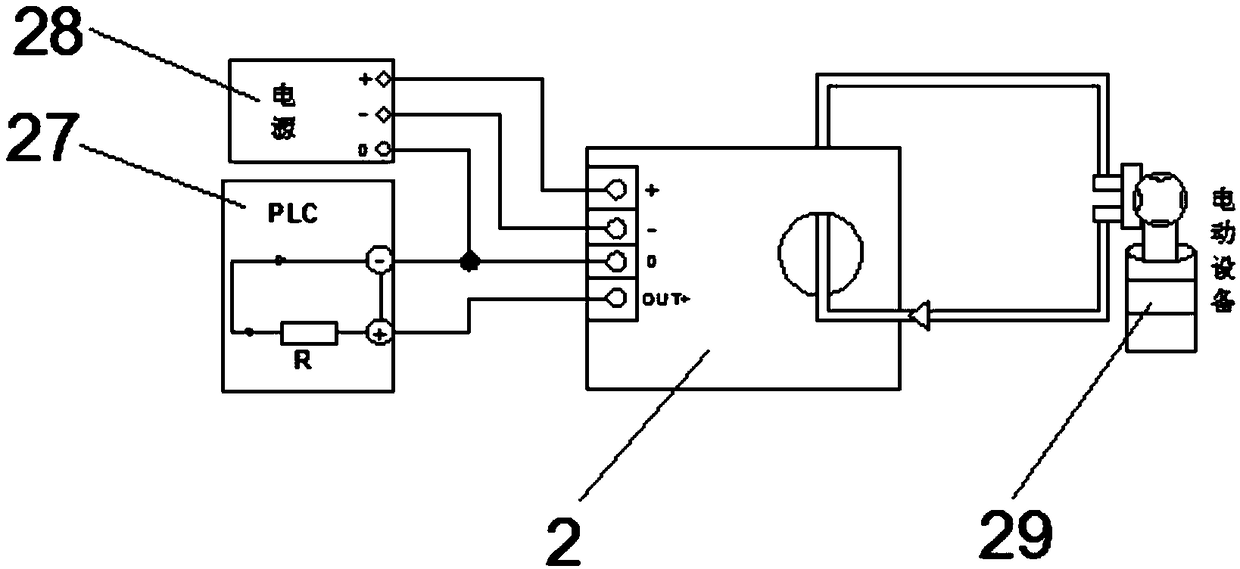
[0021] Such as Figure 1-Figure 3 As shown, a current sensor testing device proposed by the present invention includes an equipment fixing frame 1, a sensor 2 and a gear box 16. The inner bottom of the equipment fixing frame 1 is provided with a first chute 3, and the first chute 3 is provided with a support Block 5, the upper end of the first support block 5 is provided with a sensor base 4, the sensor base is fixedly connected to the lower support block by a fixing bolt 6, the upper end of the sensor base 4 is provided with a sensor 2, and the upper end of the sensor 2 is provided with a screw rod sliding sleeve 7, and the screw rod slides The upper end of the sleeve 7 is provided with a second support block 8, and the left and right ends of the first support block 4 and the second support block 8 are provided with runners 9;

[0022] A gear box 16 is arranged on the upper right end of the equipment fixing frame 1, and a transmission shaft 15 is arranged on the middle part o...


PUM


Abstract

The invention discloses a current sensor testing device which comprises an equipment fixing frame, a sensor and a gear box. A first sliding groove is formed in the bottom in the equipment fixing frame, and a supporting block is arranged on the first sliding groove. A sensor base is arranged at the upper end of the first supporting block, and the sensor base is fixedly connected with a lower supporting block through a fixing bolt. A sensor is arranged at the upper end of the sensor base, a screw rod sliding sleeve is arranged at the upper end of the sensor, and a second supporting block is arranged at the upper end of the screw rod sliding sleeve. When the current sensor testing device is used, an output wire to be tested is made to penetrate through hole fixing sleeves at the two ends of the equipment fixing frame, it is guaranteed that the output wire passes through an input end, a fixing rocking handle can better drive a rotating plate to rotate, a screw rod is controlled to rotate so that the screw rod sliding sleeve on the screw rod and a movable sensor are better moved towards one side, and the currents at the multiple positions of the output wire can be better tested. The supporting blocks on the upper side and the lower side can fix and support the sensor in the middle, and therefore the sensor can be stable during moving measurement.

Description

technical field [0001] The invention relates to the technical field of current sensor calibration, in particular to a current sensor testing device. Background technique [0002] A sensor is a detection device that can sense the measured information and convert the sensed information into electrical signals or other required forms of information output according to certain rules to meet the requirements of information transmission, processing, storage, and display. , recording and control requirements. Sensors have already penetrated into a wide range of fields such as industrial production, space development, ocean exploration, environmental protection, resource investigation, medical diagnosis, bioengineering, and even cultural relic protection. [0003] With the continuous development of current sensors, the scope of use of current sensors is also increasing, especially high-speed current sensors such as magnetic modulation and flux. However, the traditional current sens...

Claims


Application Information

Patent Timeline
Patent Type & Authority Applications(China)
IPC IPC(8): G01R35/00
CPCG01R35/005
Inventor 丁鑫秦京
Owner ANHUI SHUORI PHOTOELECTRIC TECH
Learn More