Telescopic compensation interface for vacuum transportation pipeline

A pipeline and transportation technology, which is applied to expansion compensation devices for pipelines, pipes/pipe joints/pipes, pipe components, etc., which can solve the problem of sleeve compensator leakage, inconvenience in laying tracks, and unsuitable displacement of vacuum transportation pipelines. Compensation and other issues to achieve the effect of low maintenance costs

Pending Publication Date: 2018-12-21
SOUTHWEST JIAOTONG UNIV
View PDF0 Cites 0 Cited by
  • Summary
  • Abstract
  • Description
  • Claims
  • Application Information

AI Technical Summary

Problems solved by technology

The sleeve type compensator is composed of three parts: the casing, the cannula and the sealing packing. It compensates the thermal deformation of the pipeline by the relative movement of the cannula and the casing. The packing is easy to wear, which causes the sleeve compensator to leak easily; when the pipe has a slight radial and angular displacement, it is easy to cause the sleeve to be stuck
The compensation amount of the bellows expansion joint is relatively small relative to its own axial dimension, and the bellows expansion joint with a long axial dimension can only compensate a relatively small displacement, which will make the distance between the two ends of the pipe connected too large, and its structure is Flexible corrugated structure, on which it is inconvenient to lay tracks, leads to too large track spacing inside two adjacent pipe ends, and vehicles cannot easily cross over
Moreover, the cost of corrugated expansion joints is relatively high
Therefore, the existing compensation methods are not suitable for displacement compensation of vacuum traffic pipelines

Method used


Image

  • Telescopic compensation interface for vacuum transportation pipeline
  • Telescopic compensation interface for vacuum transportation pipeline
  • Telescopic compensation interface for vacuum transportation pipeline

Examples


Embodiment 1

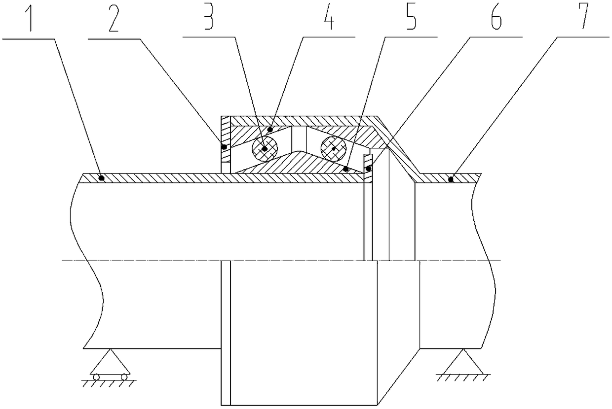
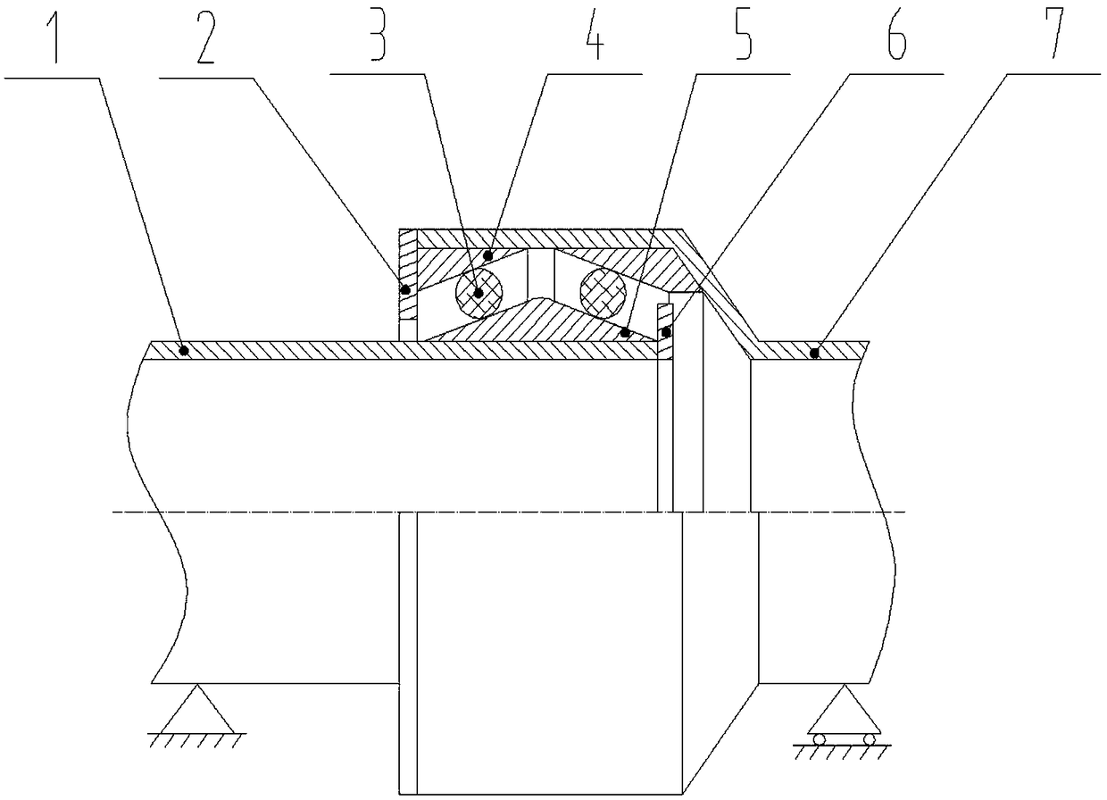
[0021] The straight end 1 of the pipeline is made of steel, which can be ordinary carbon steel, stainless steel or weathering steel. Its outer side is welded with a wedge-shaped ring 5 with a public face. The cross-section of this wedge-shaped ring is triangular. Seen from the cross-section, the two wedge-shaped faces are connected together and have a common intersection line. The surface of the wedge face needs to be smooth enough to facilitate sealing. The pipe socket end 7 is made of the same material as the pipe straight end 1, and the nested part with the pipe straight end 1 needs to be larger than the diameter of the pipe straight end 1, and there are two female surface wedge rings 4 fixed inside the pipe end, each A female wedge-shaped ring has a wedge-shaped surface, and two wedge-shaped surfaces of the male wedge-shaped ring 5 form a group of "V"-shaped ring grooves. Elastic sealing ring 3 is installed on both sides in this " V " shape ring groove. The end of the sm...

Embodiment 2

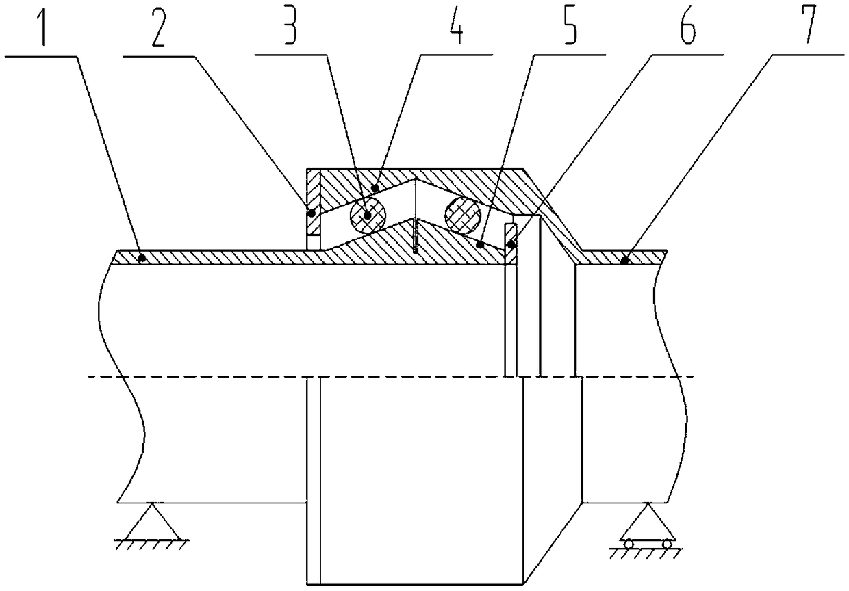
[0025] attached image 3 represents this example.

[0026] This embodiment is also composed of a pipe straight end 1 and a pipe socket end 7. The difference from Embodiment 1 is mainly that the wedge-shaped ring 5 on the public surface and the pipe straight end 1 are an integrated part instead of multiple Composition of parts; the wedge-shaped ring 4 on the female surface and the socket end 7 of the pipe are also one part, rather than composed of multiple parts. The two wedge-shaped surfaces of the wedge-shaped ring 5 on the male surface are not connected together, and there is no common line of intersection, while the two wedge-shaped surfaces of the wedge-shaped ring 4 on the female surface are connected together, and there is a common line of intersection. The elastic sealing ring 3 is also in the "V" ring groove formed by the wedge ring 4 on the female surface and the wedge ring 5 on the male surface, and cannot come out due to the limitation of the straight end baffle 6 ...

Embodiment 3

[0029] attached Figure 4 represents this example.

[0030] Embodiment 3 is basically the same as Embodiment 1, the difference is that multiple sets of wedge-shaped rings 4 on the female surface, wedge-shaped rings on the male surface 5 and elastic sealing rings 3 are arranged along the axial direction of the pipeline to form multiple sets of "V"-shaped ring grooves and elastic sealing rings. The sealing structure of ring 3. Its sealing principle is completely consistent with the implementation process, but the reliability of the sealing is enhanced by increasing the redundancy of the structure.

[0031] Implementation process is with reference to embodiment 1, both are basically the same. It's just that when one set of seals fails, the pipe remains sealed if the other set doesn't fail at the same time.


PUM


Abstract

The invention provides a telescopic compensation interface for a vacuum transportation pipeline, and relates to the technical field of vacuum pipeline compensation for vacuum rail traffic. The telescopic compensation interface for the vacuum transportation pipeline includes a pipeline straight port end, a pipeline supporting port end with an expanded joint and elastic sealing rings, the end portion of the outer diameter of the pipeline straight port end is provided with a straight port end blocking plate, the outer surface of the inner side pipe of the straight port end blocking plate is provided with a male face wedge-shaped ring, the inner surface of the pipeline supporting port end is provided with a female face wedge-shaped ring, the end portion of the inner diameter of the pipeline supporting port end is provided with a supporting end blocking plate, an inverted 'V'-shaped ring groove on the cross section of the passing axis is formed between the male face wedge-shaped ring and the female face wedge-shaped ring, and two elastic sealing rings are located on both sides of the ring groove correspondingly. The inner diameter of the female wedge-shaped ring is provided with two opposite wedge-shaped faces facing downwards on the cross section of the passing axis, and the outer diameter of the female wedge-shaped ring is fixed with the inner diameter of the pipeline supporting port end; the outer diameter of the male wedge-shaped ring is provided with two wedge-shaped faces facing away and upwards on the cross section of the passing axis, and the inner diameter of the male wedge-shaped ring is fixed with the outer diameter of the pipeline straight port end; and the two wedge-shaped faces of the female wedge-shaped ring are of the same or separate structure.

Description

technical field [0001] The invention relates to the technical field of vacuum pipeline compensation for vacuum rail transit. technical background [0002] In the post-high-speed rail era, on the one hand, it is more and more difficult to increase the speed of rail trains using wheel-rail technology; increasingly uneconomical. In this case, the application of vacuum pipeline technology to allow rail vehicles to run in pipelines in a vacuum-like environment to achieve multiple purposes such as increasing speed, reducing resistance, energy saving and environmental protection has become a new scientific research frontier in the field of rail transit technology. Southwest Jiaotong University in my country and Hyperloop One in the United States have both built vacuum tube test lines, and a research upsurge in vacuum tube trains has been set off at home and abroad. [0003] In practical application, the vacuum pipeline is under the condition of constantly changing temperature, it...

Claims


Application Information

Patent Timeline
IPC IPC(8): F16L51/00F16L27/12F16J15/18
CPCF16J15/184F16L27/12F16L51/00
Inventor 张卫华叶联龙
Owner SOUTHWEST JIAOTONG UNIV
Why Eureka
Try Eureka