Profile steel concrete transfer beam and reverse construction method thereof

A construction method and transfer beam technology, which is applied in the direction of joists, girders, truss beams, etc., can solve the problems of large cracks in steel concrete transfer beams and low utilization rate of steel materials, so as to increase the utilization rate of materials, reduce loads, and reduce Effect of number of cracks and crack width

Inactive Publication Date: 2018-12-21
CHINA RAILWAY DESIGN GRP CO LTD
View PDF7 Cites 1 Cited by
  • Summary
  • Abstract
  • Description
  • Claims
  • Application Information

AI Technical Summary

Problems solved by technology

[0003] The present invention is proposed to solve the problems of large cracks and low utilization rate of steel materials in the existing medium-sized steel concrete transfer beam, and its purpose is to provide a steel concrete transfer beam and its reverse construction method

Method used


Image

  • Profile steel concrete transfer beam and reverse construction method thereof
  • Profile steel concrete transfer beam and reverse construction method thereof
  • Profile steel concrete transfer beam and reverse construction method thereof

Examples


Embodiment 1

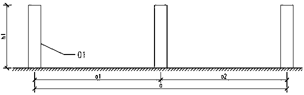
[0043] Step i. Construction of Substructure Column 1.

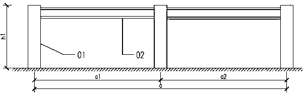
[0044] Step ii. Construct the profiled steel 2 in the steel-concrete transfer beam.

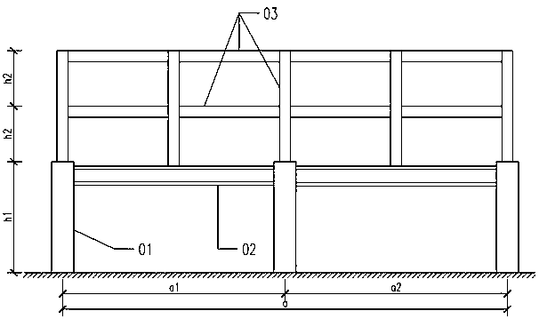
[0045] Step iii. Construct part or all of the superstructure 3 .

[0046] Step ⅳ. Construct the steel bar 4 of the steel-concrete transfer beam, and pour concrete 5 .

[0047] Step v. If there is a remaining part of the superstructure 3, construct the remaining part.

Embodiment 2

[0049] Step i. Construction of Substructure Column 1.

[0050] Step ⅱ. Construct the profiled steel 2 in the steel-concrete transfer beam, and bind the steel bars 3.

[0051] Step iii. Construct part or all of the superstructure 3 .

[0052] Step ⅳ. Concrete 5 for the construction of steel-concrete transfer beams.

[0053] Step v. If there is a remaining part of the superstructure 3, construct the remaining part.

Embodiment 3

[0055] Step i. Construction of Substructure Column 1.

[0056] Step ⅱ. Construct the profiled steel 2 in the steel-concrete transfer beam.

[0057] Step Ⅲ. Construct part or all of the superstructure 3, and bind the steel bars 4 in the steel-concrete transfer beam.

[0058] Step ⅳ. Concrete 5 for the construction of steel-concrete transfer beams.

[0059] Step v. If there is a remaining part of the superstructure 3, construct the remaining part.

[0060] Calculation is required before reverse construction to determine the construction scope of the steel section and superstructure 3, so that the steel section 2 can bear the load of the superstructure 3, and the live load of the actual situation should also be considered during design calculation and implementation.

[0061] The invention can reduce the load borne by the reinforced concrete part in the transfer beam, effectively reduce the number and width of cracks in the transfer beam to steel concrete, and simultaneously in...


PUM


Abstract

The invention discloses a profile steel concrete transfer beam and a reverse construction method thereof. The profile steel concrete transfer beam comprises lower structure columns; a transfer beam body is arranged at the upper ends of the lower structure columns; a superstructure is arranged on the transfer beam body; profile steel in the transfer beam body supports the superstructure, so that the number of steel bars in the transfer beam body is reduced and the cross section of the transfer beam body is reduced. The reverse construction method of the profile steel concrete transfer beam comprises the following steps: constructing the lower structure columns; constructing the profile steel in the transfer beam body on the lower structure columns; constructing the superstructure on the profile steel; binding profile steel external transfer beam steel bars; pouring transfer beam concrete. The profile steel concrete transfer beam disclosed by the invention has the advantages that the load borne by the reinforced concrete part in the transfer beam can be reduced, and the crack quantity and crack width of the profile steel concrete transfer beam are effectively reduced; moreover, the material utilization rate of the profile steel, relatively close to the middle part of the transfer beam, is increased.

Description

technical field [0001] The invention belongs to the technical field of civil engineering, and in particular relates to a steel-concrete transfer beam and a reverse construction method thereof. Background technique [0002] The situation of supporting columns on beams is often encountered in the design and construction of modern buildings, and it can mainly meet the requirements of large space in the lower structure. However, in this case, since the force of the upper column is directly transmitted to the supporting column conversion beam below, the beam is subjected to a huge force, resulting in a larger beam section. The use of steel concrete beams can effectively reduce the beam section, but the cracks of steel concrete beams are usually difficult to control, and the steel is close to the middle of the beam section, and its stress will be lower than the stress of the steel bars on the outer side of the steel, reducing the utilization rate of the material . Contents of t...

Claims


Application Information

Patent Timeline
Patent Type & Authority Applications(China)
IPC IPC(8): E04C3/29
CPCE04C3/293
Inventor 唐虎米宏广陈后军张小波刘晨白红刚王健
Owner CHINA RAILWAY DESIGN GRP CO LTD
Why Eureka
Try Eureka