
Boiler slag discharging device

A boiler and output-end technology, applied in the field of boiler slag removal devices, can solve the problems of residue retention, unsmooth transmission, stuck between the conveyor belt and the pipe wall, etc., and achieve the effect of reducing large slag lumps, improving the crushing effect, and avoiding the jamming effect.

Pending Publication Date: 2018-12-21
浙江杭兴锅炉有限公司
View PDF9 Cites 1 Cited by
  • Summary
  • Abstract
  • Description
  • Claims
  • Application Information

AI Technical Summary

Problems solved by technology

[0003] Existing boilers use the heat energy generated by the combustion of solid combustion materials to heat water to increase the temperature of the water and convert energy. However, after the combustion of solid combustion materials such as coal, large residues may remain due to insufficient combustion. When the slag discharge device is conveying waste slag, large pieces of residue will be stuck between the conveyor belt and the pipe wall, resulting in unsmooth transmission

Method used


Image

  • Boiler slag discharging device
  • Boiler slag discharging device
  • Boiler slag discharging device

Examples


Embodiment Construction

[0021] The present invention will be further described in detail below in conjunction with the examples, the following examples are explanations of the present invention and the present invention is not limited to the following examples. Apparently, the described embodiments are only some of the embodiments of the present invention, but not all of them. Based on the embodiments of the present invention, all other embodiments obtained by persons of ordinary skill in the art without making creative efforts belong to the protection scope of the present invention. In addition, the terms "first", "second", "third", etc. are used for descriptive purposes only and should not be construed as indicating or implying relative importance. At the same time, in the description of the present invention, unless otherwise clearly stipulated and limited, the terms "connected" and "connected" should be understood in a broad sense, for example, it can be a fixed connection, a detachable connectio...


PUM


Abstract

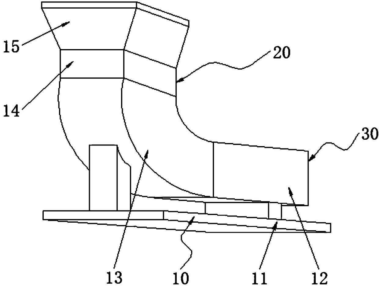
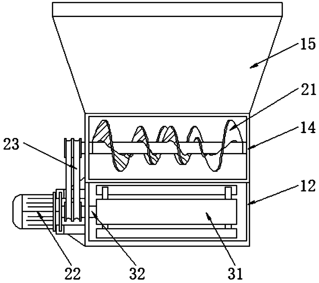
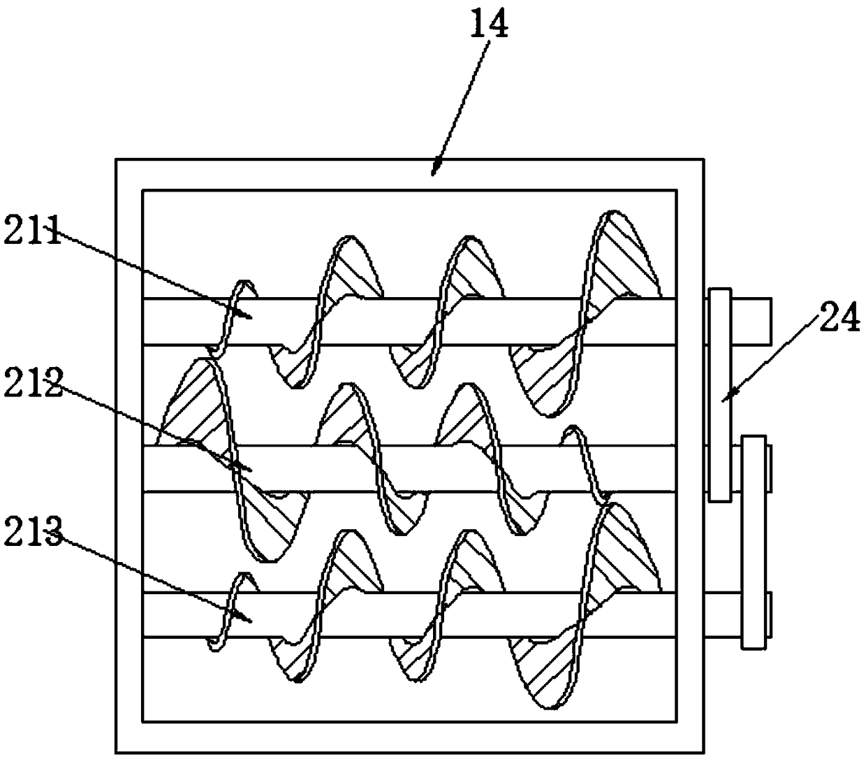
The invention belongs to the technical field of boiler auxiliary devices, and particularly relates to a boiler slag discharging device. The device comprises a machine body assembly, a pulverizing assembly and a conveying assembly. The machine body assembly comprises a rack, a conveying channel, a guiding channel, a pulverizing chamber and a material receiving hopper. The rack is fixed to the ground, and the conveying channel is located above the rack. A transmission belt is used for driving pulverizing rollers to rotate, a better pulverizing effect can be achieved through the three cone spiralpulverizing rollers, and generation of large slag blocks is reduced. The two ends of the pulverizing rollers are rotationally connected with the pulverizing chamber, every two pulverizing rollers arein transmission connection through an auxiliary transmission belt, it can be guaranteed that the pulverizing rollers have power input, and the phenomenon of belt jamming is avoided. The guiding and pulverizing functions can be conducted on crushed slag, accordingly, a better pulverizing effect is achieved, every two adjacent pulverizing rollers are placed in a staggered manner, and a better crushed slag pulverizing effect is achieved through a reasonable structure.

Description

technical field [0001] The invention belongs to the technical field of boiler auxiliary devices, and in particular relates to a boiler slag discharge device. Background technique [0002] The main working principle of the boiler is a kind of thermal equipment that uses the heat energy released after fuel combustion or the waste heat in industrial production to transfer to the water in the container to make the water reach the required temperature or steam at a certain pressure. The two parts of the "furnace" are carried out at the same time. After the water enters the boiler, the heat absorbed by the heating surface of the boiler in the steam-water system will be transferred to the water, so that the water will be heated into hot water with a certain temperature and pressure or steam will be drawn out for application. In the combustion equipment part, Fuel combustion continuously releases heat, and the high-temperature flue gas generated by combustion transfers heat to the h...

Claims


Application Information

Patent Timeline
Patent Type & Authority Applications(China)
IPC IPC(8): B02C13/20B02C13/30B02C13/286
CPCB02C13/20B02C13/286B02C13/30B02C2013/28672B02C2013/28609
Inventor 金伟明
Owner 浙江杭兴锅炉有限公司
Learn More