Power conversion device
a power converter and power technology, applied in the direction of dc-ac conversion without reversal, ac network load balancing, emergency power supply arrangement, etc., can solve the problem of limited input power to the rectifier to the upper limit value, and achieve the effect of increasing the input power to the second power converter, and reducing the size of the cooler
- Summary
- Abstract
- Description
- Claims
- Application Information
AI Technical Summary
Benefits of technology
Problems solved by technology
Method used
Image
Examples
first embodiment
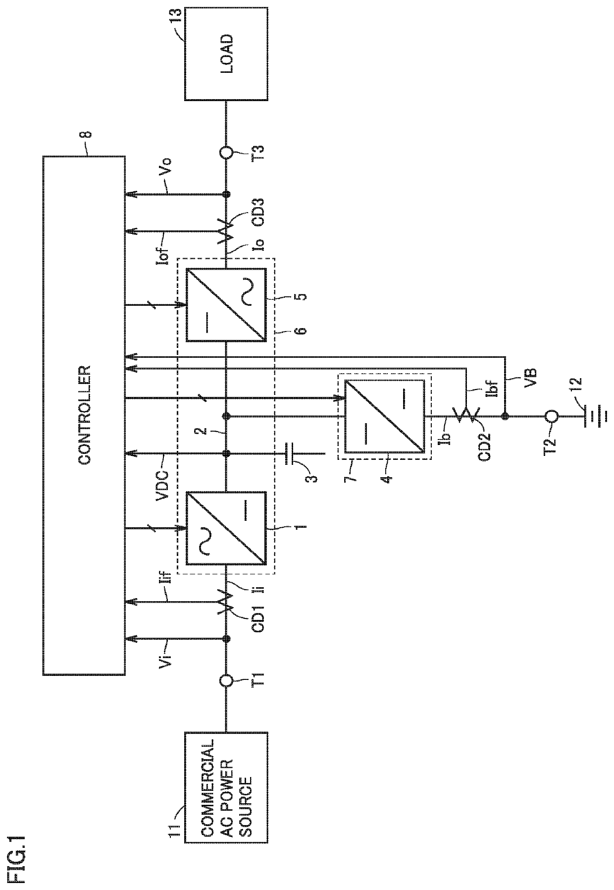
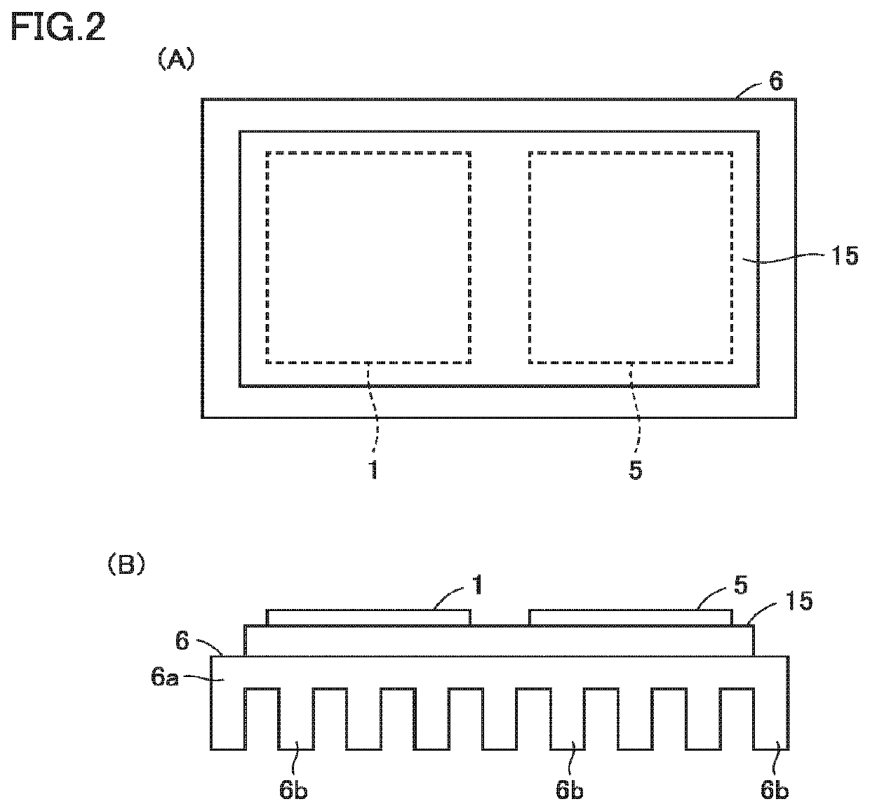
[0020]FIG. 1 is a block diagram showing the configuration of an uninterruptible power supply according to a first embodiment of the present invention. In FIG. 1, this uninterruptible power supply includes an input terminal T1, a battery terminal T2, an output terminal T3, current detectors CD1 to CD3, a converter 1, a DC line 2, a capacitor 3, a bidirectional chopper 4, an inverter 5, coolers 6, 7, and a controller 8.
[0021]Input terminal T1 receives AC power having a commercial frequency from a commercial AC power source 11 (first power source). Battery terminal T2 is connected to a battery 12 (second power source). Battery 12 stores DC power. A capacitor may be connected instead of battery 12. Output terminal T3 is connected to a load 13. Load 13 is driven with AC power having a commercial frequency supplied from the uninterruptible power supply.
[0022]Converter 1, DC line 2 and inverter 5 are connected in series between input terminal Ti and output terminal T3. Capacitor 3 is conne...
second embodiment
[0078]FIG. 9 is a block diagram showing the configuration of an uninterruptible power supply according to a second embodiment of the present invention, which is shown as compared with FIG. 1. Referring to FIG. 9, this uninterruptible power supply differs from the uninterruptible power supply in FIG. 1 in that input terminal T1 is connected to a DC power source 61, converter 1 is replaced by a DC-DC converter 62, and controller 8 is replaced by a controller 8A.
[0079]DC power source 61 (first power source) is a fuel cell, for example, which generates DC power and outputs the generated power to input terminal T1. An instantaneous value of a DC voltage VI supplied from DC power source 61 is detected by controller 8A. Current detector CD1 detects input current Ii to DC-DC converter 62, and outputs signal Iif indicating the detected value to controller 8A.
[0080]Controller 8A controls each of DC-DC converter 62, bidirectional chopper 4, and inverter 5 based on DC voltage VI, AC output volt...
third embodiment
[0091]FIG. 10 is a block diagram showing the configuration of an uninterruptible power supply according to a third embodiment of the present invention, which is shown as compared with FIG. 1. Referring to FIG. 10, this uninterruptible power supply differs from the uninterruptible power supply in FIG. 1 in that battery terminal T2, bidirectional chopper 4 and controller 8 are replaced by an AC terminal T4, a converter 71 and a controller 8B, respectively, and that AC terminal T4 is connected to an AC generator 72.
[0092]AC generator 72 (second power source) generates AC power and outputs the generated power to AC terminal T4. An instantaneous value of an AC voltage Va output from AC generator 72 is detected by controller 8B. Current detector CD2 detects an input current Ia to converter 71, and outputs a signal Iaf indicating the detected value to controller 8B.
[0093]Controller 8B controls each of converters 1, 71 and inverter 5 based on DC voltage VI, AC output voltage Vo, DC voltage ...
PUM
 Abstract
Description
Claims
Application Information
 - R&D Engineer
- R&D Manager
- IP Professional
- Industry Leading Data Capabilities
- Powerful AI technology
- Patent DNA Extraction
Browse by: Latest US Patents, China's latest patents, Technical Efficacy Thesaurus, Application Domain, Technology Topic, Popular Technical Reports.
© 2024 PatSnap. All rights reserved.Legal|Privacy policy|Modern Slavery Act Transparency Statement|Sitemap|About US| Contact US: help@patsnap.com


