
An acoustic barrier for noise reduction in an outdoor substation

A technology for sound barriers and substations, applied in power distribution substations, anti-seismic equipment, etc., can solve the problems of poor weather resistance of sound barrier materials, decline in the overall performance of sound barriers, and increased noise energy loss, etc., to achieve good weather resistance and easy promotion and use , the effect of excellent strength

Inactive Publication Date: 2018-12-18
GLOBAL ENERGY INTERCONNECTION RES INST CO LTD +2
View PDF6 Cites 1 Cited by
  • Summary
  • Abstract
  • Description
  • Claims
  • Application Information

AI Technical Summary

Problems solved by technology

Among them, controlling from the source is the most effective method, but it is difficult to control and the cycle is long. It is still in the research stage in our country, and it is rarely put into practical application. At present, the substations in service mainly adopt noise reduction control on the sound source propagation path , for substations that have been built and have been in stable operation for many years, it is quite difficult to update low-noise equipment and control the distance between substations and people's living, activities, and workplaces. , noise reduction and other measures to increase the energy loss of noise in the transmission path, to achieve the purpose of reducing noise pollution
[0004] Sound barrier is a commonly used noise reduction measure in substations, especially in the high-frequency band, the sound insulation effect is better, but the noise energy of substations is mainly low-frequency noise; The material puts forward very high requirements, but the existing sound barrier materials have poor weather resistance, and the weathering phenomenon is serious after long-term work, resulting in a rapid decline in the overall performance of the sound barrier

Method used


Image

  • An acoustic barrier for noise reduction in an outdoor substation
  • An acoustic barrier for noise reduction in an outdoor substation
  • An acoustic barrier for noise reduction in an outdoor substation

Examples


Embodiment 1

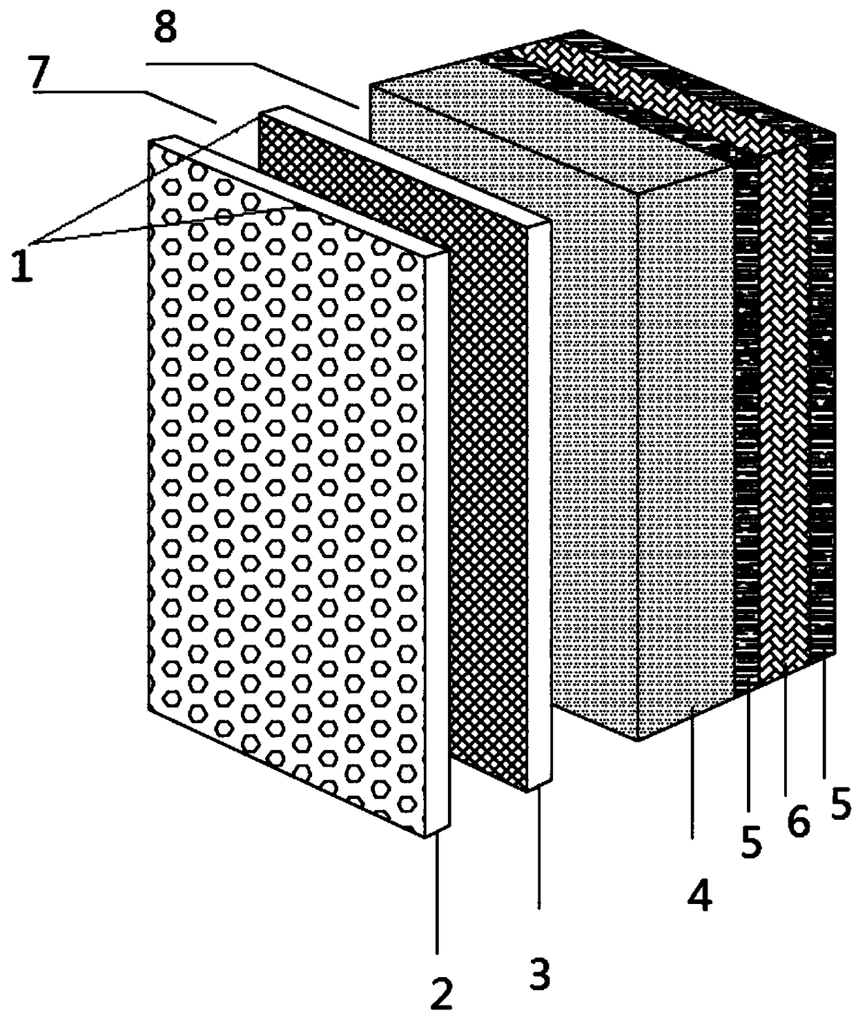
[0033] like figure 1 As shown, a sound barrier for outdoor substation noise reduction, the thickness of the sound barrier is 100mm; the sound barrier includes a microporous fiber composite sound-absorbing board 1, a rock wool board 4, a constrained damping board and a cavity, the The microporous fiber composite sound-absorbing board 1, the rock wool board 4 and the constrained damping board are placed in sequence in the horizontal direction, and the constrained damping board is located on the outermost side of the sound barrier; the microporous fiber composite sound-absorbing board 1 includes the inner layer The micro-perforated plate 2 and the outer aluminum fiber plate 3; a first cavity 7 is provided between the micro-perforated plate 2 and the aluminum fiber plate 3, and a second cavity 8 is provided between the aluminum fiber plate 3 and the rock wool plate 4;

[0034] The horizontal thickness of the first cavity 7 between the micro-perforated plate 2 and the aluminum fibe...

Embodiment 2

[0044] A sound barrier for outdoor substation noise reduction, the thickness of the sound barrier is 128mm; the sound barrier includes a microporous fiber composite sound-absorbing board, a rock wool board, a constrained damping plate and a cavity, and the microporous fiber composite sound-absorbing The sound board, the rock wool board and the constrained damping board are placed in sequence, and the constrained damping board is located on the outermost side of the sound barrier; the microporous fiber composite sound-absorbing board includes micro-perforated boards and aluminum fiber boards from the inside to the outside, and the micro-perforated There is a first cavity between the aluminum fiber board and the aluminum fiber board, and a second cavity between the aluminum fiber board and the rock wool board;

[0045] The distance in the horizontal direction of the first cavity between the micro-perforated plate and the aluminum fiber plate is 40mm;

[0046] The plate thickness...

Embodiment 3

[0053]A sound barrier for noise reduction in an outdoor substation, the thickness of the sound barrier is 150mm; the sound barrier comprises a microporous fiber composite sound-absorbing board, a rock wool board, a restraint damping board and a cavity, and the The sound board, the rock wool board and the constrained damping board are placed in sequence, and the constrained damping board is located at the outermost side of the sound barrier; the microporous fiber composite sound-absorbing board includes a micro-perforated board and an aluminum fiber board from the inside to the outside. A first cavity is provided between the board and the aluminum fiber board, and a second cavity is provided between the aluminum fiber board and the rock wool board;

[0054] The spacing in the horizontal direction of the first cavity between the micro-perforated board and the aluminum fiber board is 35 mm;

[0055] The thickness of the micro-perforated plate is 1 mm, the aperture is 1.5 mm, and ...


PUM

PropertyMeasurementUnit
thicknessaaaaaaaaaa
thicknessaaaaaaaaaa
thicknessaaaaaaaaaa

Abstract

The invention provides an acoustic barrier for noise reduction in an outdoor substation. The acoustic barrier comprises a microporous fiber composite sound absorbing plate, a rock wool plate, a restraining damping plate and a cavity. The microporous fiber composite sound absorbing plate, the rock wool plate and the constraint damping plate are arranged in order in the horizontal direction; The microporous fiber composite sound absorbing board comprises an inner layer microperforated board and an outer layer aluminum fiberboard; A first cavity is arranged between the micro-perforated board andthe aluminum fiberboard, and a second cavity is arranged between the aluminum fiberboard and the rock wool board. The sound barrier provided by the invention has wide sound insulation frequency band,good weather resistance, good mechanical performance and adjustable acoustic performance.

Description

technical field [0001] The invention relates to a sound barrier, in particular to a sound barrier for outdoor substation noise reduction. Background technique [0002] With the rapid development of modern economy and society, the power load is increasing day by day, resulting in higher and higher transmission voltage levels, and high-voltage and ultra-high-voltage outdoor substations are becoming more and more common. Because the main transformers and power distribution devices of outdoor substations are open The noise source can spread freely to the outside world. Excessive noise in substations has become an urgent problem to be solved in substations, and it also affects the development of power grid construction to a certain extent. [0003] Noise control measures are basically controlled from two aspects: sound source and sound source propagation path. Among them, controlling from the source is the most effective method, but it is difficult to control and the cycle is lo...

Claims


Application Information

Patent Timeline
Patent Type & Authority Applications(China)
IPC IPC(8): H02B1/54H02B7/06C08L9/02C08L15/00C08L13/00C08L27/06
CPCC08L9/02C08L2205/035H02B1/54H02B7/06C08L15/005C08L13/00C08L27/06
Inventor 何强聂京凯李睿卢林汪美顺潘巍巍赵深
Owner GLOBAL ENERGY INTERCONNECTION RES INST CO LTD
Learn More