Eureka AIR delivers breakthrough ideas for toughest innovation challenges, trusted by R&D personnel around the world.

An active phased array antenna based on a cellular skeleton and an array composition method thereof

A technology for phased array antennas and antenna arrays, which is applied in the direction of individually energized antenna arrays, antenna arrays, and devices for manufacturing antenna arrays. Sparse array design method is difficult and other problems, to achieve the effect of simplifying the calculation workload, ensuring the accuracy of calculation, and weakening the ability

Active Publication Date: 2018-12-18
CHINA ELECTRONIC TECH GRP CORP NO 38 RES INST
View PDF9 Cites 5 Cited by
  • Summary
  • Abstract
  • Description
  • Claims
  • Application Information

AI Technical Summary

Problems solved by technology

The limited field of view scanning phased array antenna increases the spacing between antenna elements and sacrifices the scanning ability of the antenna array to achieve the purpose of sparse active channels. This method has a narrow application range and a limited active channel sparse ratio; A certain proportion of sparse elements is used. This method can sparse the number of antenna elements and active channels in a large proportion, and effectively suppress the scanning grating lobes. However, the sparse array design method is difficult, and the sparse antenna array has different shapes and is difficult to process, assemble, and Positioning; using irregular sub-arrays to break the periodicity of sub-array arrangements can also achieve sparse active channels and suppress scanning grating lobes, but the composition of irregular sub-arrays is difficult, and it is not easy to implement for large-scale active phased array projects

Method used


Image

  • An active phased array antenna based on a cellular skeleton and an array composition method thereof
  • An active phased array antenna based on a cellular skeleton and an array composition method thereof
  • An active phased array antenna based on a cellular skeleton and an array composition method thereof

Examples


Embodiment Construction

[0035] The embodiments of the present invention are described in detail below. This embodiment is implemented on the premise of the technical solution of the present invention, and detailed implementation methods and specific operating procedures are provided, but the protection scope of the present invention is not limited to the following implementation example.

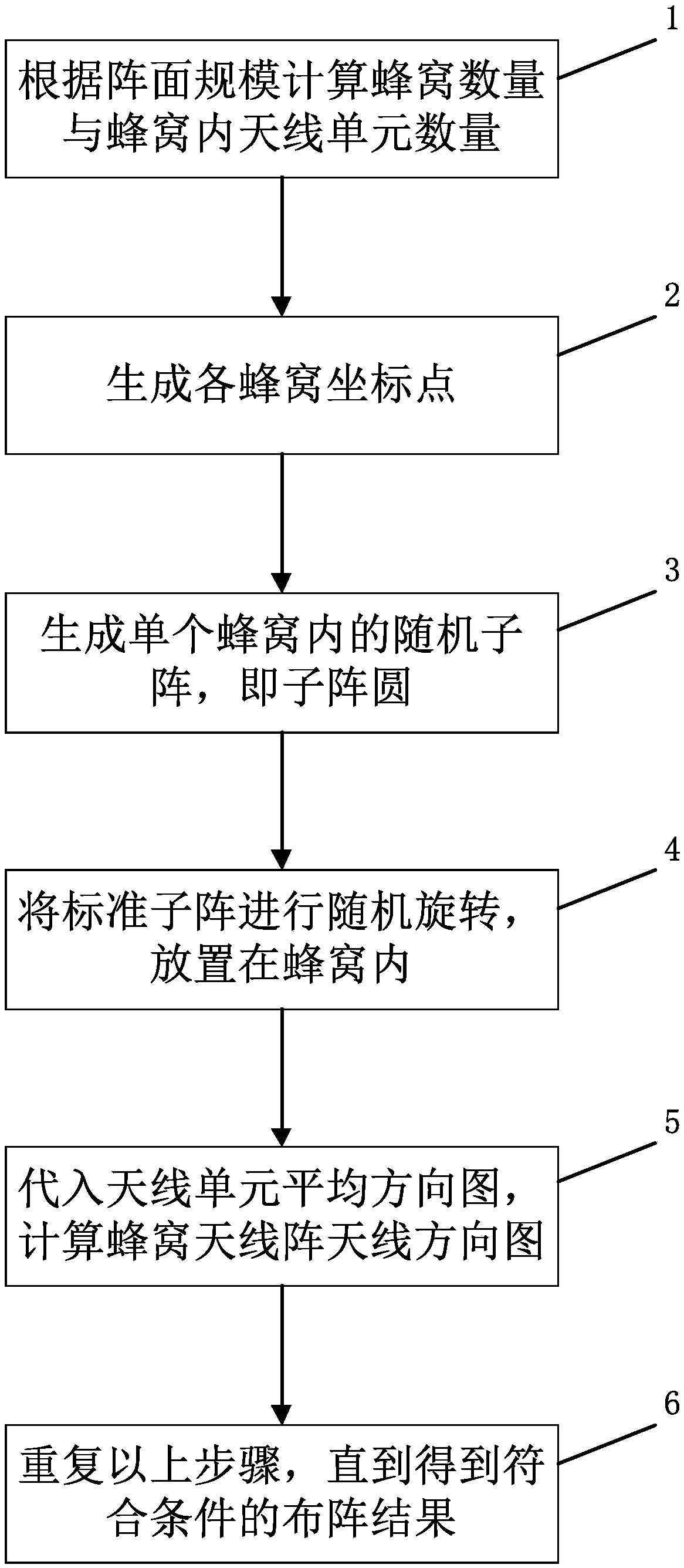
[0036] Such as figure 1 As shown, this embodiment includes the following steps:

[0037] (1) Calculate the number of cells and the number of antenna units 2 in the cells according to the scale of the array;

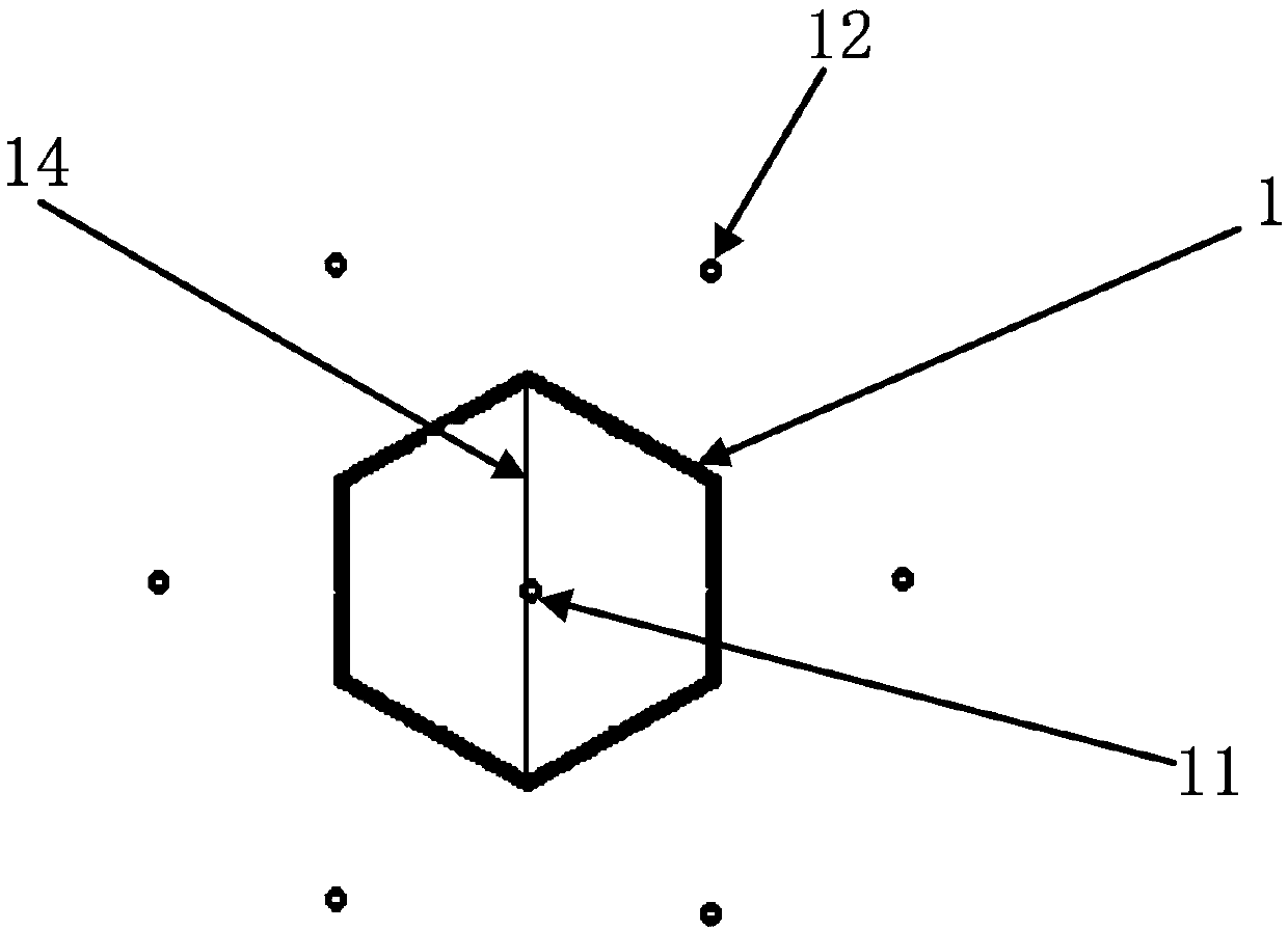
[0038] (2) generate each cellular coordinate point, and each cellular is closely arranged in the cellular antenna array;

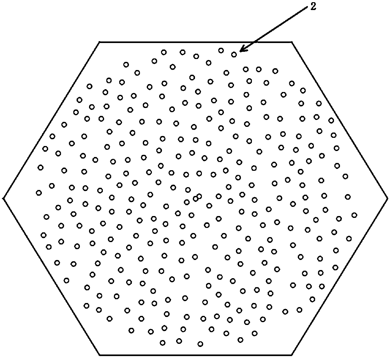
[0039] (3) Generate random sub-arrays in the honeycomb, i.e. sub-array circle 3;

[0040] (4) The sub-array circle 3 is randomly rotated and installed in each honeycomb;

[0041] (5) Substituting the average pattern of the antenna unit 2 to calculate the pattern of the cellular antenna...


PUM


Abstract

The invention discloses an active phased array antenna based on a honeycomb skeleton and an array forming method thereof. The number of the honeycomb and the number of the antenna units in the honeycomb are calculated according to the front scale. Generating each cellular coordinate point, and closely arranging each cellular in the cellular antenna array; Generating a random submatrix in a honeycomb, namely a submatrix circle; A subarray circle is randomly rotate and installed in each honeycomb; The pattern of cellular antenna array is calculated by substituting the average pattern of antennaelements. Repeat the above steps until the array results meet the requirements. The random distribution of antenna elements in the subarray circle and the random rotation of the subarray produce the antenna array with strong randomness of antenna element distribution, effectively destroy the superposition of the pattern scanning grating lobe in the radiation space, and weaken the scanning gratinglobe.

Description

technical field [0001] The invention relates to an active phased array radar technology, in particular to an active phased array antenna based on a honeycomb skeleton and an array formation method thereof. Background technique [0002] With the rapid development of modern radar technology, the requirements of radar in space surveillance and detection, theater early warning and attack assessment, combat operation plan and combat plan require active phased array antennas to develop in the direction of large-scale and broadband work. (The electrical size is the physical size of the antenna relative to the working frequency wavelength) to improve system performance such as radar resolution and power. Although the cost of phased array radar has dropped significantly with the development of science and technology and technological progress, it is still daunting. Huge equipment and power consumption are important factors affecting the application of phased array. How to make the a...

Claims


Application Information

Patent Timeline
Patent Type & Authority Applications(China)
IPC IPC(8): H01Q1/36H01Q21/00H01Q21/06
CPCH01Q1/36H01Q21/0087H01Q21/061
Inventor 孙立春侯田朱杨张洪涛汪伟金谋平鲁加国
Owner CHINA ELECTRONIC TECH GRP CORP NO 38 RES INST
Why Eureka
Eureka Blog
Learn More