Thimble anti-collision structure and thimble module

A thimble and anti-collision technology, applied in the direction of electrical components, semiconductor/solid-state device manufacturing, circuits, etc., can solve the problem that the thimble module is easy to be bumped and damaged

Active Publication Date: 2018-12-18
广东阿达智能装备有限公司
View PDF5 Cites 0 Cited by
  • Summary
  • Abstract
  • Description
  • Claims
  • Application Information

AI Technical Summary

Problems solved by technology

[0003] Based on this, it is necessary to provide a thimble anti-collision structure and a thimble module for

Method used


Image

  • Thimble anti-collision structure and thimble module
  • Thimble anti-collision structure and thimble module
  • Thimble anti-collision structure and thimble module

Examples


Embodiment Construction

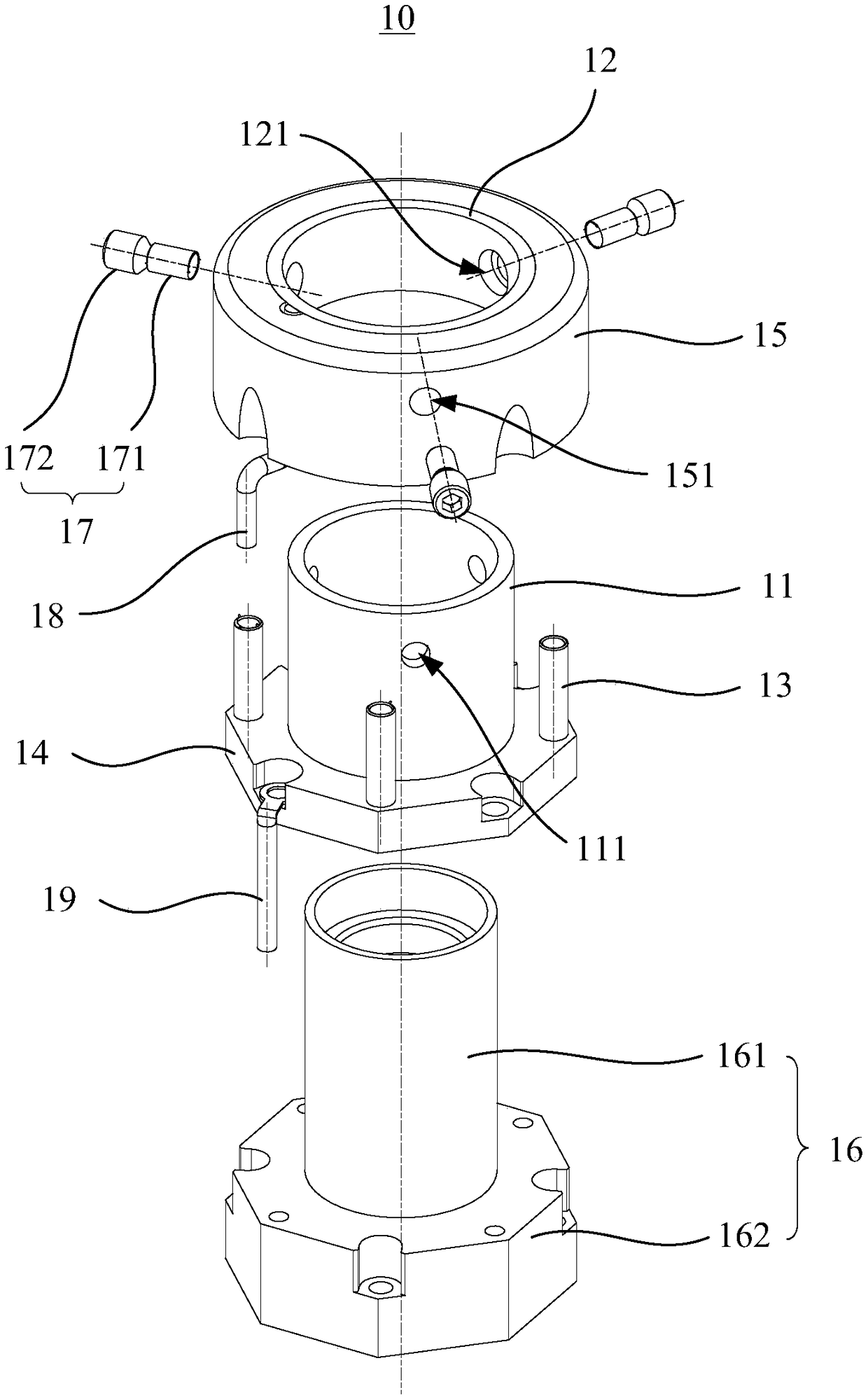
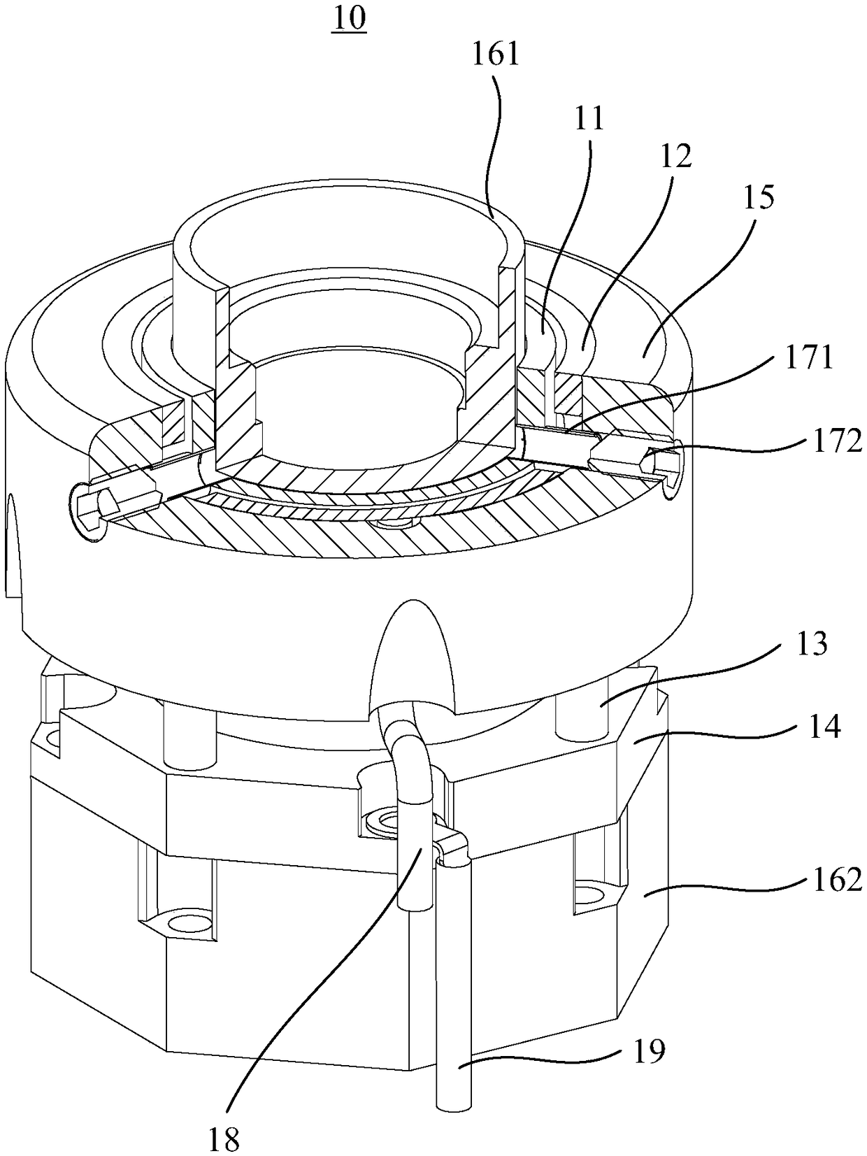
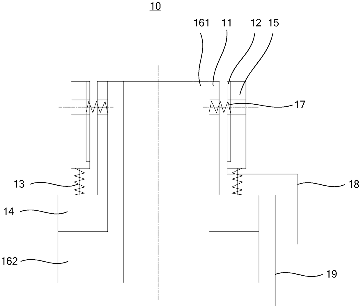
[0021] Such as Figure 1 to Figure 3 As mentioned, in one embodiment, a thimble anti-collision structure 10 is provided, which includes a conductive cylinder 11 capable of inserting a thimble and a conductive ring 12 sleeved on the periphery of the conductive cylinder 11, and the outer periphery of the conductive cylinder 11 is provided with elastic Support 13, one end of the elastic support 13 is connected to the conductive cylinder 11, and the other end of the elastic support 13 is connected to the conductive ring 12. When working normally, the conductive cylinder 11 is connected to the conductive cylinder 11. The conductive ring 12 is arranged at intervals, and the power is off between them. When an external object strikes, the conductive ring 12 moves relative to the conductive barrel 11, and the conductive ring 12 contacts the conductive barrel 11 to be energized.

[0022] The above solution provides a thimble anti-collision structure 10. In normal use, the conductive ring 1...


PUM


Abstract

The invention relates to a thimble anti-collision structure and a thimble module. The thimble anti-collision structure comprises a conductor barrel capable of inserting the thimble and a conductive ring sleeved on the periphery of the conductor barrel, the outer periphery of the electric conductor is provided with an elastic supporting member, one end of the elastic support is connected with the electric conductor, the other end of the elastic support is connected with the conductive ring, when working normally, the conductor is spaced apart from the conductive ring, the power is off between the two, when an external object strikes, the conductive ring moves relative to the torch, the conductive ring is in contact with the torch and energized, and the controller controls the workbench to stop emergency or control the thimble module to move downward according to the signal of the conductive ring and the torch contacting and energized, so as to avoid the thimble module from being crashed.

Description

Technical field [0001] The invention relates to the field of semiconductor post packaging, in particular to a thimble anti-collision structure and a thimble module. Background technique [0002] In the semiconductor manufacturing process, the crystal grains formed through processes such as deposition, sputtering, and etching also need to be packaged subsequently to protect the internal structure and prevent external impurities from entering and affecting performance. In the process of post-semiconductor packaging, it is necessary to realize the crystal taking process through the thimble module. Specifically, after the blue film of the wafer is expanded, the ejector pin of the ejector module lifts the wafer upward, and the corresponding suction nozzle adsorbs the wafer to complete the crystal removal process. In the process of taking the crystal, the ejector module only moves in the vertical direction to complete the process of lifting the wafer. The worktable moves on the horiz...

Claims


Application Information

Patent Timeline
IPC IPC(8): H01L21/687
CPCH01L21/68742
Inventor 贺云波刘青山王波刘凤玲陈桪
Owner 广东阿达智能装备有限公司
Why Eureka
Try Eureka