
Device debugging method, system and apparatus, computer device and storage medium

A debugging method and computer program technology, applied in the direction of control/regulation system, test/monitoring control system, general control system, etc., can solve the problems of affecting the production cycle, prolonging the research and development cycle, and prolonging the PLC debugging time, so as to achieve full program, Guarantee the production cycle and shorten the effect of R&D cycle

Inactive Publication Date: 2018-12-18
BEIJING JUNTAIINNOVATION TECH CO LTD
View PDF9 Cites 4 Cited by
  • Summary
  • Abstract
  • Description
  • Claims
  • Application Information

AI Technical Summary

Problems solved by technology

[0005] Based on this, it is necessary to provide an equipment debugging method, system, device, computer equipment and storage medium

Method used


Image

  • Device debugging method, system and apparatus, computer device and storage medium
  • Device debugging method, system and apparatus, computer device and storage medium
  • Device debugging method, system and apparatus, computer device and storage medium

Examples


Embodiment Construction

[0074] In order to make the purpose, technical solution and advantages of the present application clearer, the present application will be further described in detail below in conjunction with the accompanying drawings and embodiments. It should be understood that the specific embodiments described here are only used to explain the present application, and are not intended to limit the present application.

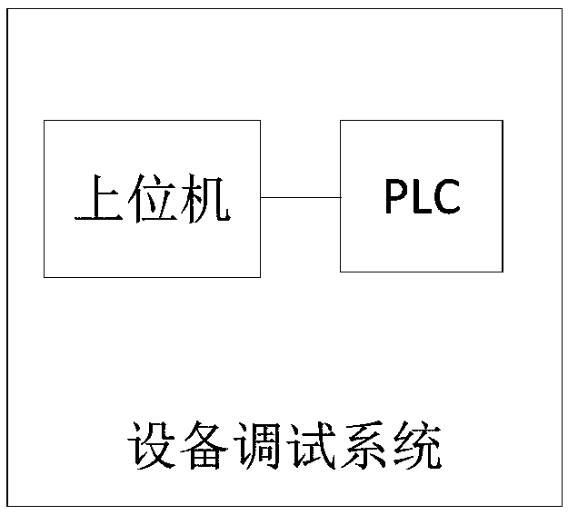
[0075] The device debugging method provided by this application can be applied to such as figure 1 In the equipment debugging system shown, the equipment debugging system includes a PLC and a host computer. The upper computer can communicate with the PLC, and the communication method between the upper computer and the PLC can be wired communication, and the wired communication can be Ethernet, OLE (Object Linking and Embedding for Process Control, OPC for short) for process control, or on-site bus communication, etc. There can also be wireless communication between the u...


PUM


Abstract

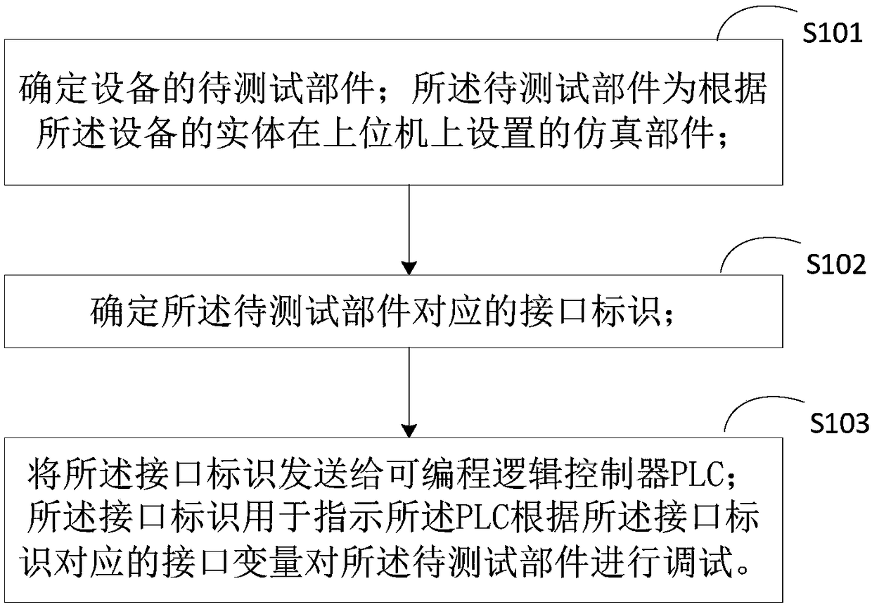
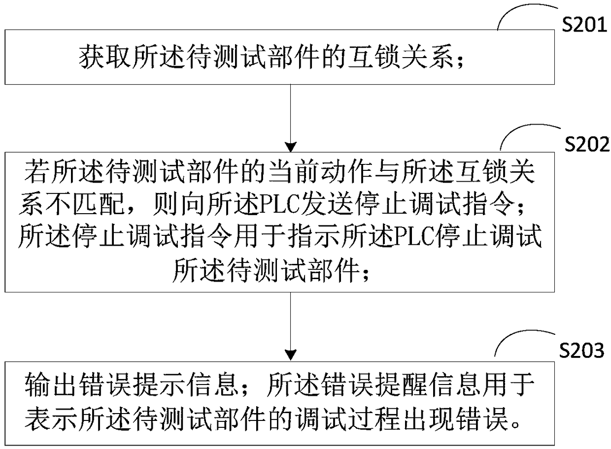
The invention provides a device debugging method, system and apparatus, a computer device and a storage medium. The method comprises the following steps: determining a to-be-tested component of a device through an upper computer, obtaining an identifier of the to-be-tested component, correspondingly determining an interface identifier corresponding to the to-be-tested component, and then sending,by the upper computer, the interface identifier to a PLC that communicates with the upper computer. In this way, a real action effect is simulated by a simulation component of the to-be-tested component of the device in the upper computer, the operation condition of the to-be-tested component under the control of a PLC program is visually reflected through animation, so that the debugging personnel can be effectively helped to complete the debugging task, and the debugging program of the method is more sufficient as a result. The PLC is under the control of the upper computer, only the upper computer and the PLC are adopted, the device can be debugged in advance without connecting the real device the production site, so that the subsequent time occupied by the debugging of the PLC programis greatly shortened, and the research and development cycle of a project is shortened, so that a normal production cycle is ensured.

Description

technical field [0001] The present invention relates to the technical field of equipment debugging, in particular to an equipment debugging method, system, device, computer equipment and storage medium. Background technique [0002] Programmable Logic Controller (PLC) is a digital operation electronic system specially designed for application in industrial environments. With the development of PLC technology, PLC has been widely used in various fields. For example, in the automatic control of production equipment, PLC technology is often used to debug the equipment. [0003] Generally, the debugging of equipment using PLC technology is mainly for debugging personnel to go to the production site for debugging. The debugging personnel will write the program written in advance for the equipment into the PLC, and then connect with the normal working equipment that has been assembled at the production site. Debugging, modify the corresponding PLC program in time for the problems...

Claims


Application Information

Patent Timeline
Patent Type & Authority Applications(China)
IPC IPC(8): G05B19/05G05B23/02
CPCG05B19/058G05B23/0213G05B2219/163
Inventor 朱哲明张津岩张凤港杨娜
Owner BEIJING JUNTAIINNOVATION TECH CO LTD
Learn More