Optical fiber coupler based on circular polarization, and manufacturing and use methods thereof
A technology of optical fiber coupler and manufacturing method, which is applied in the coupling of optical waveguide, light guide, optics, etc., can solve the problems of single function and increase the complexity of optical system, and achieve the effects of simple preparation, reduced complexity, and small insertion loss
- Summary
- Abstract
- Description
- Claims
- Application Information
AI Technical Summary
Problems solved by technology
Method used
Image
Examples
Embodiment 1
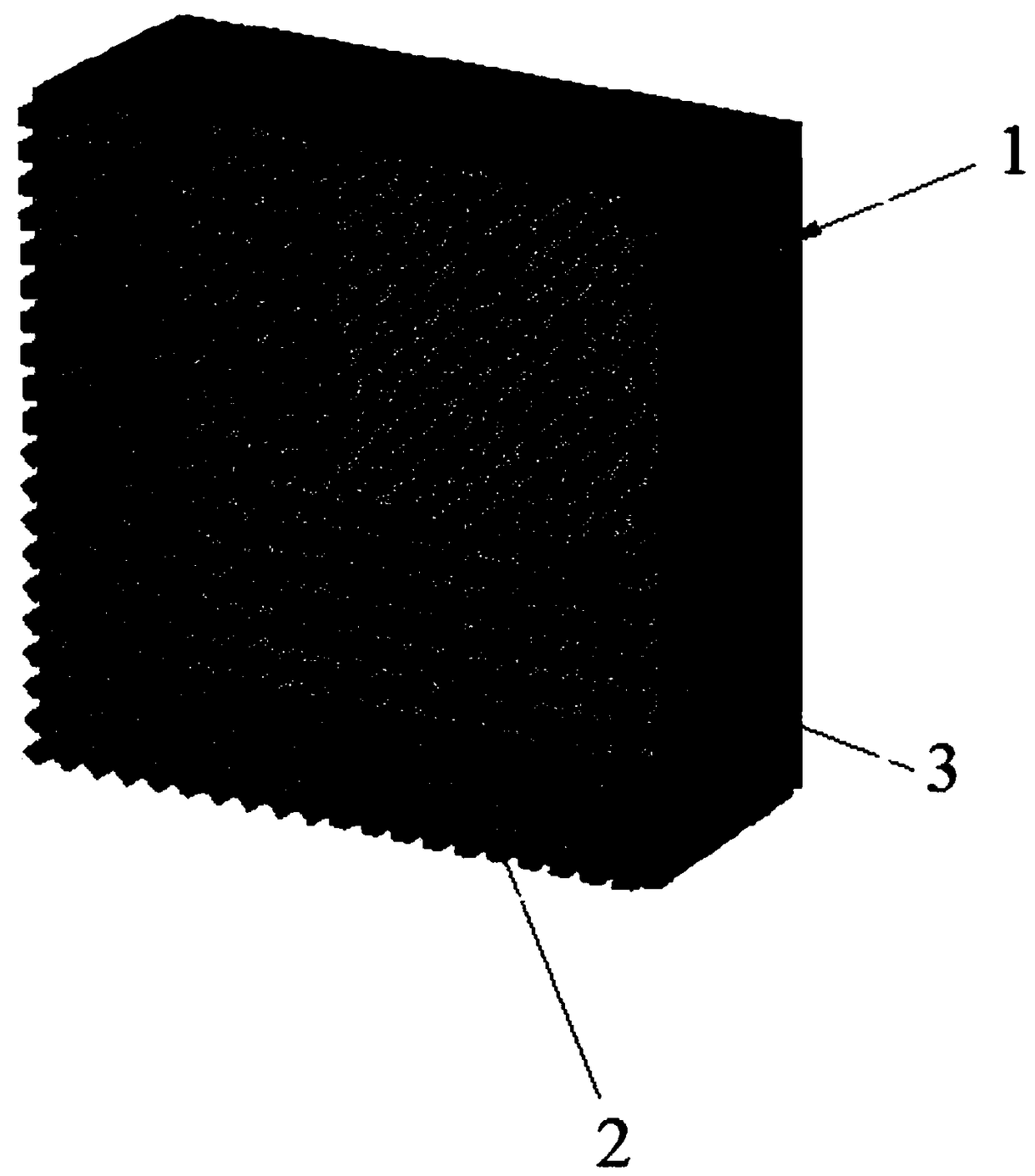
[0033] see figure 1 As shown, the embodiment of the present invention provides a fiber coupler based on circular polarization. The fiber coupler is made of a metasurface material, including a substrate 1 and a silicon nanorod array. The silicon nanorod array is formed by a plurality of silicon nanorod units 2 etched on the substrate 1. The structural parameters of the silicon nanorods 3 in the same silicon nanorod unit 2 are the same, and the silicon nanorod units 2 in different silicon nanorod units 2 are arranged. The structural parameters of the nanorods 3 are different, that is, the silicon nanorod units 2 are divided according to the structural parameters of the silicon nanorods 3 .
[0034] Different silicon nanorod units 2 are arranged on the corresponding substrate 1 with different rotation angles α(i, j), and the rotation angle is the angle between the long axis of the silicon nanorod 3 and the x-axis in the coordinate system xoy of the working surface, and satisfies ...
Embodiment 2
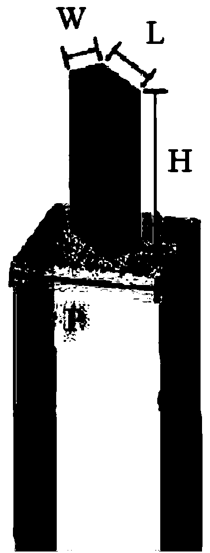
[0051] see Figure 1-2 As shown, the embodiment of the present invention provides a method for manufacturing a fiber coupler based on circular polarization, including the following steps:
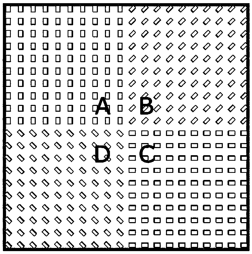
[0052] S1: Make sure the working wavelength is 1550nm, in order to convert the incident left-handed circularly polarized light into LP 11amode, the incident right-handed circularly polarized light is converted to LP 11b mode, it was determined that four different silicon nanorod units were required, see image 3 As shown, the silicon nanorod array is divided into four silicon nanorod units, which are marked as A, B, C and D units in the figure, and for the left-handed circularly polarized incident light, the A, B, C and D regions produce The phase delays of are 0, π, π, 0, respectively; for the right-handed circularly polarized incident light, the phase delays generated by regions A, B, C, and D are 0, 0, π, π, respectively.
[0053] The rotation angle α(i, j) of different silicon nanoro...
Embodiment 3
[0058] The embodiment of the present invention also provides a method for using the above optical fiber coupler, including the following steps:
[0059] S1: Combine the modulated left-handed circularly polarized light and right-handed circularly polarized light through the beam combiner 4, and the combined light is vertically incident on a fiber coupler 5 to form LP respectively 11a mode and the higher-order modes of the LP11b mode, the resulting LP 11a and LP 11b The normalized electric field intensity distribution of the mode is as Figure 4 shown;
[0060] S2: Different high-order modes are coupled into a few-mode fiber or a multi-mode fiber through a 4f system composed of a collimator lens 6 and a focusing lens 7 to realize fiber mode multiplexing, see Figure 5 shown.
[0061] S3: Two high-order modes propagating for a certain distance in a few-mode fiber or a multi-mode fiber are incident on the silicon nanorod array of another fiber coupler to form left-handed polar...
PUM
 Abstract
Description
Claims
Application Information
 - Generate Ideas
- Intellectual Property
- Life Sciences
- Materials
- Tech Scout
- Unparalleled Data Quality
- Higher Quality Content
- 60% Fewer Hallucinations
Browse by: Latest US Patents, China's latest patents, Technical Efficacy Thesaurus, Application Domain, Technology Topic, Popular Technical Reports.
© 2025 PatSnap. All rights reserved.Legal|Privacy policy|Modern Slavery Act Transparency Statement|Sitemap|About US| Contact US: help@patsnap.com


