Load balancing device and flying probe testing device with balancing device
A balancing device and load balancing technology, which is applied in the field of flying probe testing machines, can solve problems such as large torque of guiding devices, and achieve the effect of prolonging life
- Summary
- Abstract
- Description
- Claims
- Application Information
AI Technical Summary
Problems solved by technology
Method used
Image

Examples
Embodiment 1
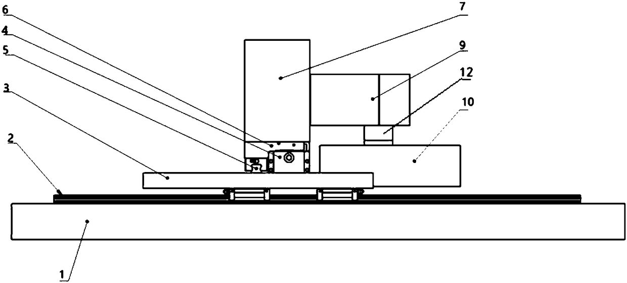
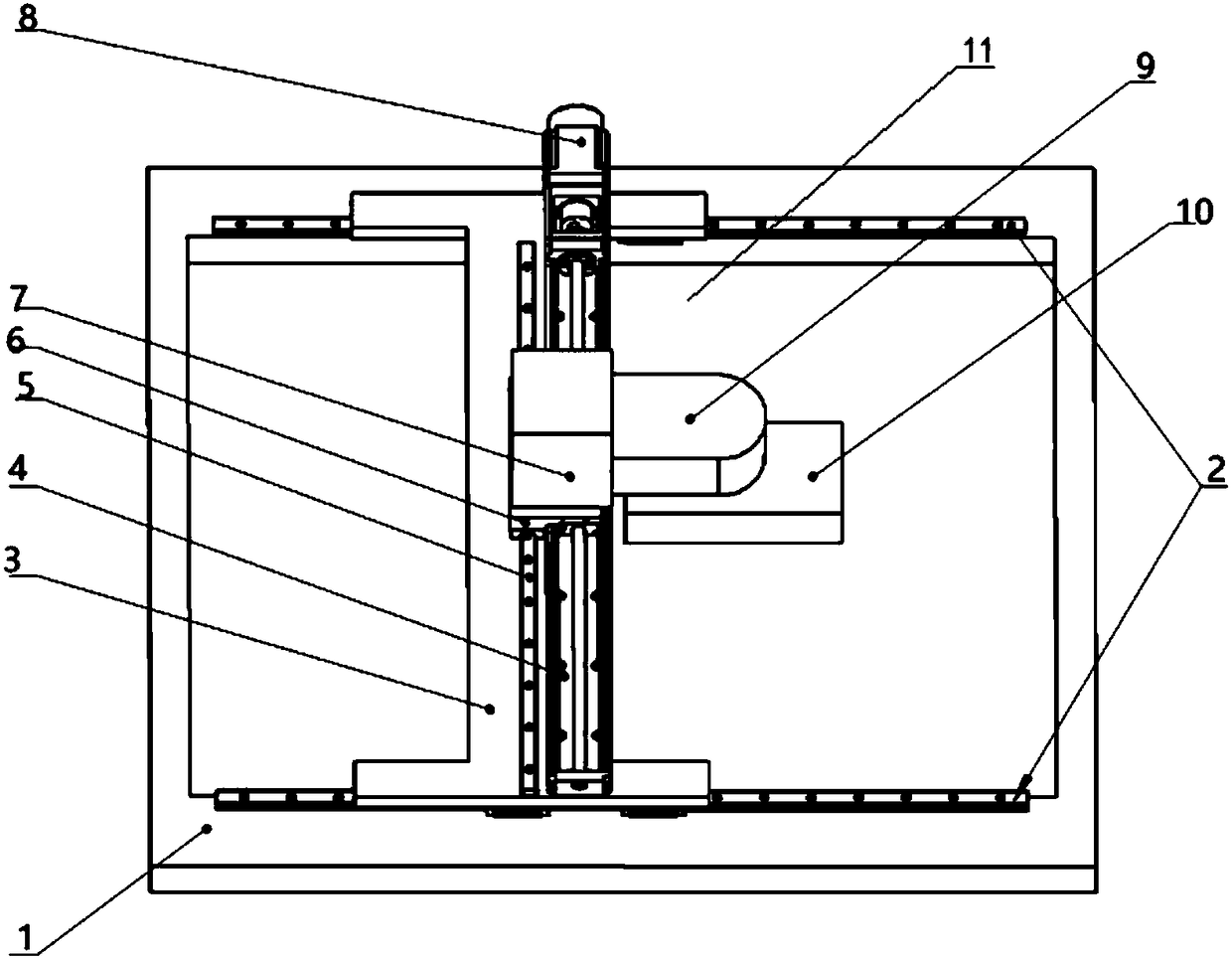
[0057] The present invention provides a plane flying probe testing machine and a test head balancing device for the flying probe testing machine, wherein the flying probe testing machine includes a base 1, and the base 1 is horizontally arranged, such as figure 1 The shown base 1 is a frame-shaped structure, the middle of which constitutes the test area 11 . Wherein, above and below the base 1, there are flying probe test devices with the same structure using the base 1 as the installation support base. The flying probe test device includes: a pair of X-axis assemblies 2 fixedly installed on the base 1, two sets of X-axis assemblies 2 are arranged on opposite sides of the base 1 in parallel, and the X-axis assemblies 2 guide the test head during the test. Movement along the X axis in area 11. Above the X-axis assembly 2, a Y-axis assembly 4 is arranged vertically across two groups of X-axis assemblies 2 and perpendicular to the X-axis assembly 2, and a rotating test head (not...
Embodiment 2
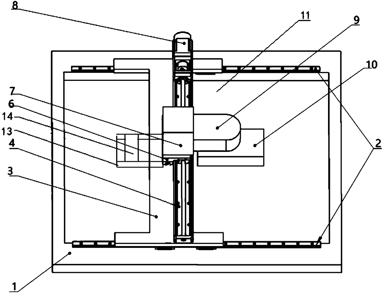
[0064] In the second embodiment of the present invention, the basic structure of the flying probe testing device is the same as that of the first embodiment, and the difference from the first embodiment lies in the arrangement of the balancing device. In the second embodiment, the balancing device includes a counterweight guide rail 13 arranged along the reverse extension line of the cantilever 9 , and a counterweight 14 slidable on the counterweight guide rail 13 . The counterweight guide rail 13 can be arranged and installed on the end of the connecting block 6 through a connecting member, and the counterweight guide rail 13 and the cantilever 9 are respectively arranged on both sides of the connecting block 6 . In the process of sliding connection between the counterweight 14 and the counterweight guide rail 13, by adjusting the distance between the counterweight 14 and the Y-axis linear module, the torque of the balance device on the Y-axis linear module can be adjusted, th...
Embodiment 3
[0066] In the third embodiment of the present invention, the basic structure of the flying probe testing device is the same as that of the above-mentioned embodiment, and the difference from the above-mentioned embodiment lies in the arrangement of the balance device and the arrangement of the Y-axis assembly. In this embodiment 3, the Y-axis assembly adopts the screw rod 15; and the balance device includes balance guide rails 5 arranged on both sides of the Y-axis screw rod and parallel to it, similar to the balance guide rails in embodiment 1, two balance guide rails The guide rails 5 are respectively arranged on both sides of the linear screw rod 15, and are set at a certain distance from the screw rod. Theoretically, the larger the distance between the two balance guide rails 5 and the Y-axis screw rod 15, the better the balancing effect they play, and In order to meet the use environment with high bearing strength, the balance guide rail in this embodiment also uses a roll...
PUM
 Abstract
Description
Claims
Application Information
 - Generate Ideas
- Intellectual Property
- Life Sciences
- Materials
- Tech Scout
- Unparalleled Data Quality
- Higher Quality Content
- 60% Fewer Hallucinations
Browse by: Latest US Patents, China's latest patents, Technical Efficacy Thesaurus, Application Domain, Technology Topic, Popular Technical Reports.
© 2025 PatSnap. All rights reserved.Legal|Privacy policy|Modern Slavery Act Transparency Statement|Sitemap|About US| Contact US: help@patsnap.com