Light and small target continuously launching device
A target device, light and small technology, applied in the direction of weapon accessories, ammunition supply, offensive equipment, etc., can solve the problems that it is difficult to realize the continuous launch of flat-headed ammunition, and it is not suitable for the launch of light and small targets, so as to achieve continuous launch and safe launch process Effect
- Summary
- Abstract
- Description
- Claims
- Application Information
AI Technical Summary
Problems solved by technology
Method used
Image

Examples
specific Embodiment approach 1
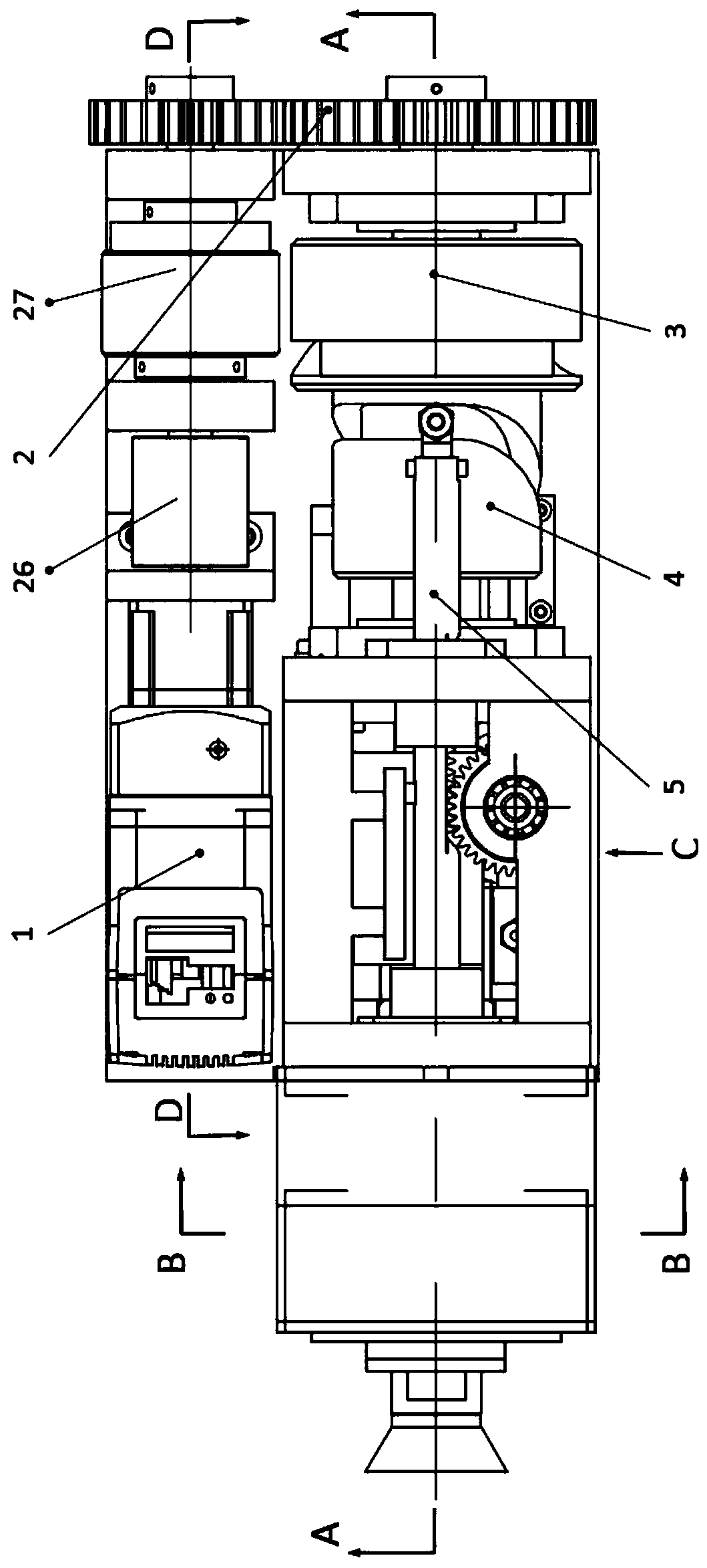
[0030] Specific implementation mode one: combine figure 1 , figure 2 , image 3 , Figure 4 , Image 6 and Figure 8Describe this embodiment mode, a kind of continuous launch light small target device of this embodiment mode, it comprises driving system, transmission system, bomb feeding system, launching and ejecting system and supporting system; Driving system comprises motor 1, speed reducer 26 and clutch 27 , the motor 1 is installed on the motor support frame 25 of the support system, the speed reducer 26 is used in conjunction with the motor 1, and the speed reducer 26 is connected with the clutch 27; Between the drive system and the bomb feeding system and the launch and ejection system; the transmission system includes a first space cylindrical cam 3 and a second space cylindrical cam 4 that move synchronously, and the first space cylindrical cam 3 and the second space cylindrical cam 4 are coaxially arranged , the first space cylindrical cam 3 is provided with a...
specific Embodiment approach 2
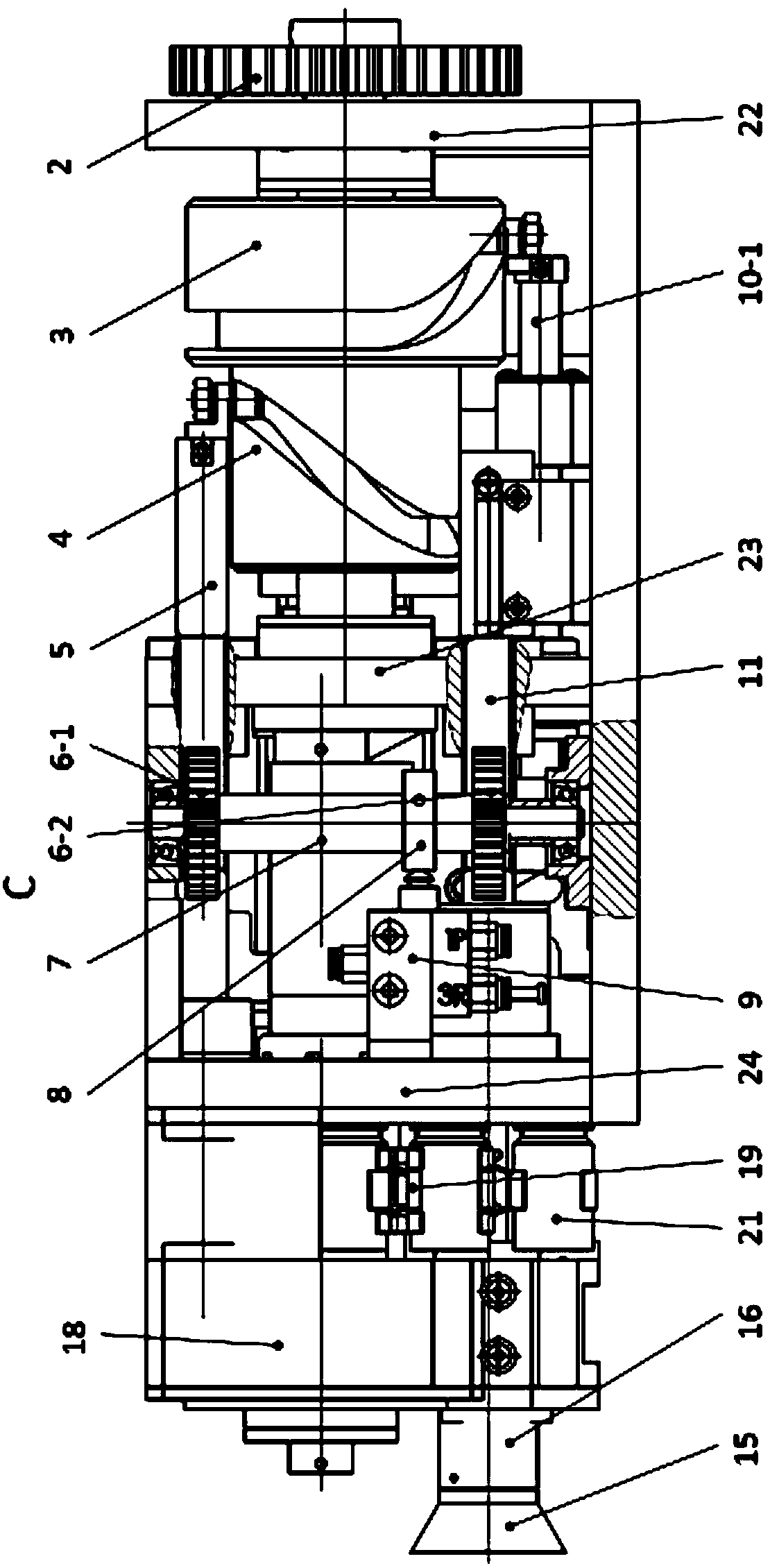
[0034] Specific implementation mode two: combination Figure 1 to Figure 3 Describe this embodiment, the transmission system of this embodiment also includes a gear reducer 2, and the gear reducer 2 is arranged between the first space cylindrical cam 3 and the clutch; the gear reducer 2 includes a drive system output shaft, a transmission system input gear, The output shaft of the transmission system and the output gear of the transmission system; the output shaft of the drive system is connected with the output shaft of the clutch in the drive system, the input gear of the transmission system is installed on the output shaft of the drive system, and the output shaft of the transmission system is installed on the rear end support frame of the support system 22 Above, the output gear of the transmission system is installed on the output shaft of the transmission system, the output gear of the transmission system meshes with the input gear of the transmission system, and the outp...
specific Embodiment approach 3
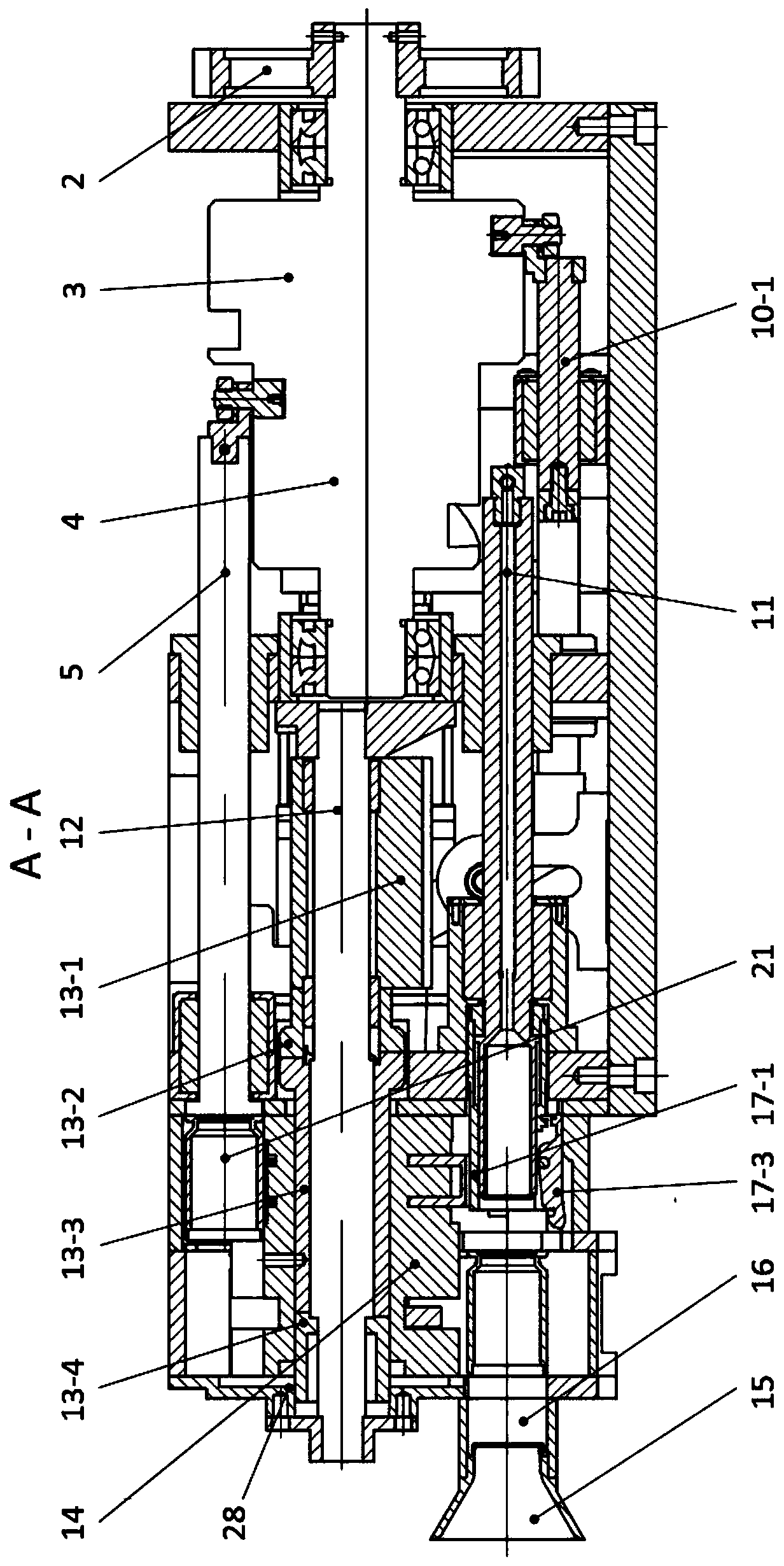
[0037] Specific implementation mode three: combination image 3 , Figure 4 , Image 6 and Figure 8 To illustrate this embodiment, the ratchet mechanism of the bomb feeding system of this embodiment also includes an active ratchet 13-2, a transmission ratchet 13-3, a stop ratchet 13-4, a first recoil spring 13-5 and a guide mandrel 12; The third space cylindrical cam 13-1 is fixedly connected with the driving ratchet 13-2, the driving ratchet 13-3 is located between the driving ratchet 13-2 and the stop ratchet 13-4, and one end of the driving ratchet 13-3 is connected to the driving ratchet 13- 2 Cooperate, the other end of the transmission ratchet 13-3 cooperates with the non-directional ratchet 13-4, and the guide mandrel 12 passes through the non-directional ratchet 13-4, the transmission ratchet 13-3, and the driving ratchet 13-2 sequentially from front to back And the third space cylindrical cam 13-1; the first return spring 13-5 is installed between the ratchet whee...
PUM
 Abstract
Description
Claims
Application Information
 - Generate Ideas
- Intellectual Property
- Life Sciences
- Materials
- Tech Scout
- Unparalleled Data Quality
- Higher Quality Content
- 60% Fewer Hallucinations
Browse by: Latest US Patents, China's latest patents, Technical Efficacy Thesaurus, Application Domain, Technology Topic, Popular Technical Reports.
© 2025 PatSnap. All rights reserved.Legal|Privacy policy|Modern Slavery Act Transparency Statement|Sitemap|About US| Contact US: help@patsnap.com