Circulating cooling device and using method thereof
A technology for circulating cooling and cooling pipelines, which is applied in the field of electric power and can solve the problem that the circulating cooling device cannot operate normally.
- Summary
- Abstract
- Description
- Claims
- Application Information
AI Technical Summary
Problems solved by technology
Method used
Image


Examples
Embodiment 1
[0030] According to an embodiment of the present invention, a circulating cooling device is provided, such as figure 1 As shown, the device includes:
[0031] The cooling pipeline 10 , the return pipeline 20 , the first heat exchanger 30 and the radiator 40 .
[0032] Wherein, one end of the cooling pipeline 10 is connected to the inlet of the radiator 40 , so that the fluid in the cooling pipeline 10 absorbs the heat of the radiator 40 ; one end of the return pipeline 20 is connected to the outlet of the radiator 40 . The cooling pipeline 10 and the return pipeline 20 pass through the first heat exchanger 30 , so that the fluid in the return pipeline 20 absorbing heat from the radiator 40 preheats the fluid in the cooling pipeline 10 . The other end of the return line 20 communicates with the other end of the cooling line 10 .
[0033] Specifically, combined with figure 1 , taking the circulating cooling device of the diverter valve as an example, since the diverter valve ...
Embodiment 2
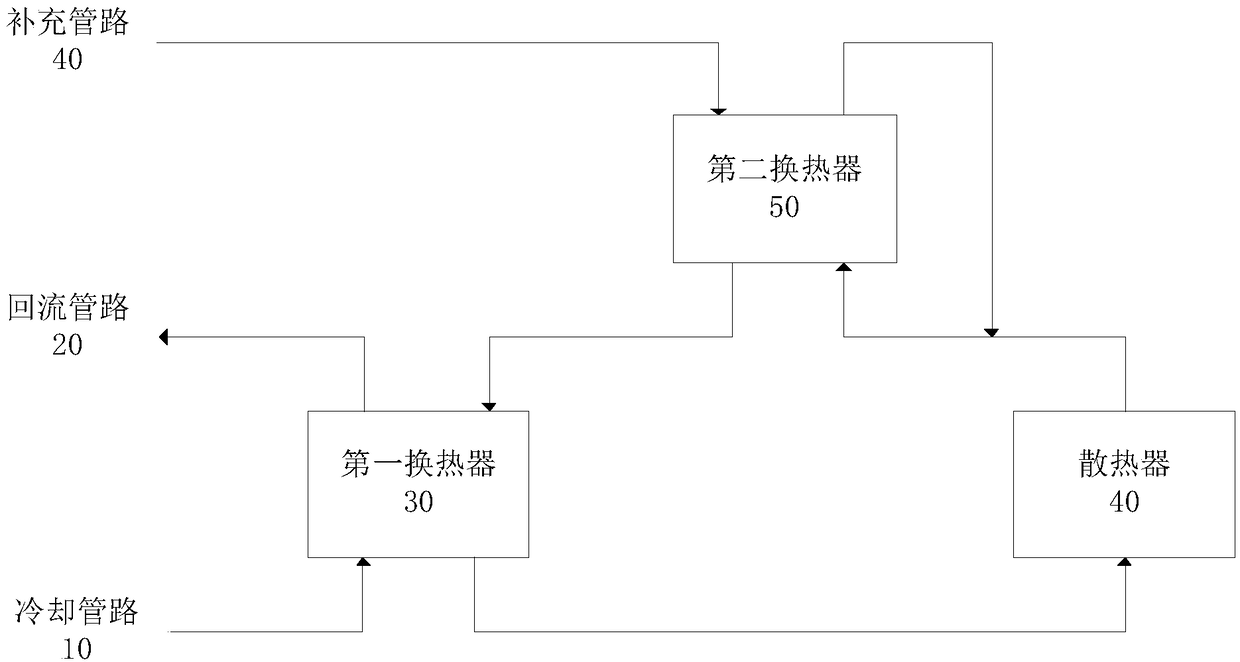
[0040] According to an embodiment of the present invention, a circulating refrigeration device is provided, such as figure 2 As shown, the device includes:
[0041] Cooling line 10 , return line 20 , supplementary line 40 , first heat exchanger 30 , second heat exchanger 50 and radiator 40 .
[0042] Wherein, one end of the cooling pipeline 10 is connected to the inlet of the radiator 40 , so that the fluid in the cooling pipeline 10 absorbs the heat of the radiator 40 ; one end of the return pipeline 20 is connected to the outlet of the radiator 40 . The cooling pipeline 10 and the return pipeline 20 pass through the first heat exchanger 30 , so that the fluid in the return pipeline 20 absorbing heat from the radiator 40 preheats the fluid in the cooling pipeline 10 . The other end of the return line 20 communicates with the other end of the cooling line 10 . One end of the supplementary pipeline 40 communicates with the return pipeline 20 for replenishing the fluid to the...
Embodiment 3
[0050] According to an embodiment of the present invention, a circulating refrigeration device is provided, such as image 3 As shown, the device includes:
[0051] A first pipe provided with a first valve 31; a second pipe provided with a second valve 32, one end of the second pipe communicated with one end of the first pipe; a third pipe provided with a third valve 33; A fourth pipe provided with a fourth valve 34, one end of the fourth pipe communicates with an end of the third pipe; a fifth pipe provided with a fifth valve 35, one end of which communicates with the other end of the fourth pipe communicated; the sixth pipe provided with the sixth valve 36, one end communicates with the other end of the first pipe; the first heat exchanger 30, its first outlet communicates with the other end of the second pipe, the first The inlet communicates with the other end of the sixth pipe, the second inlet communicates with the other end of the third pipe, and the second outlet comm...
PUM
 Abstract
Description
Claims
Application Information
 - R&D
- Intellectual Property
- Life Sciences
- Materials
- Tech Scout
- Unparalleled Data Quality
- Higher Quality Content
- 60% Fewer Hallucinations
Browse by: Latest US Patents, China's latest patents, Technical Efficacy Thesaurus, Application Domain, Technology Topic, Popular Technical Reports.
© 2025 PatSnap. All rights reserved.Legal|Privacy policy|Modern Slavery Act Transparency Statement|Sitemap|About US| Contact US: help@patsnap.com