
Shield tunnel back-filled grouting auxiliary mechanism and grouting method

A technology of back wall grouting and shield tunneling, which is applied in tunnels, tunnel linings, earth-moving drilling and mining, etc., can solve the problems of limited floating effect of controlling segments, water leakage, affecting normal traffic opening and tunnel structure safety, etc.

Pending Publication Date: 2018-12-18
SUN YAT SEN UNIV
View PDF6 Cites 12 Cited by
  • Summary
  • Abstract
  • Description
  • Claims
  • Application Information

AI Technical Summary

Problems solved by technology

However, the above-mentioned method for controlling the floating of segments has limited effect on controlling the floating of segments, and it cannot be controlled in a specific area (large floating area)
In addition, during the operation of the tunnel, if the grouting is not dense and the external water pressure is too large (water-rich formation), leakage may occur due to the plugging of the hoisting hole in the middle of the segment (also used as the grouting hole behind the wall) falls off Water accidents, which seriously affect the normal traffic and tunnel structure safety

Method used


Image

  • Shield tunnel back-filled grouting auxiliary mechanism and grouting method
  • Shield tunnel back-filled grouting auxiliary mechanism and grouting method
  • Shield tunnel back-filled grouting auxiliary mechanism and grouting method

Examples


Embodiment Construction

[0027] The technical solutions in the embodiments of the present invention will be clearly and completely described below in conjunction with the accompanying drawings. Obviously, the described embodiments are only a part of the embodiments of the present invention, rather than all the embodiments. Based on the embodiments of the present invention, all other embodiments obtained by those of ordinary skill in the art without creative work shall fall within the protection scope of the present invention.

[0028] It should be noted that if there are directional indications (such as up, down, left, right, front, back, top, bottom, inside, outside, vertical, horizontal, vertical, counterclockwise, clockwise, circumferential) in the embodiment of the present invention, Direction, radial, axial...), the directional indication is only used to explain the relative positional relationship, movement, etc. between the components in a specific posture (as shown in the figure), if the specific ...


PUM


Abstract

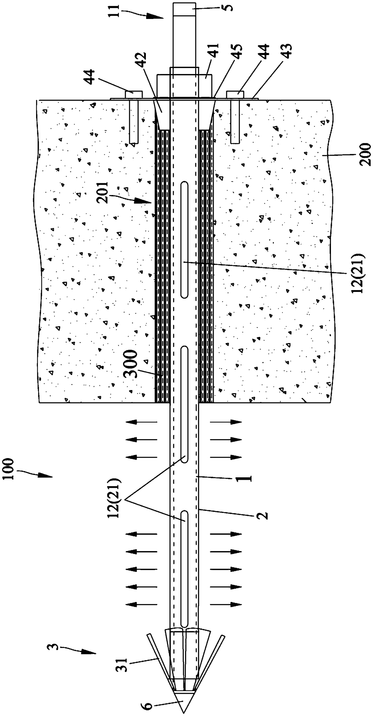
The invention discloses a shield tunnel back-filled grouting auxiliary mechanism and a grouting method. A slurry inlet and a first slurry exit, communicating with a cavity, are arranged in the back end and the circumferential wall of an inner rod. A second slurry exit corresponding to the first slurry exit is arranged in a sleeve which is in screwed connection with the inner rod. An anchoring piece arranged in front of the sleeve is installed on the part, inserted into a surrounding rock layer, of the inner rod. On one hand, the slurry radially flows out through the first slurry exit and the second slurry exit, so the reactive force on the outer wall of a pipe sheet imposed by the slurry can be greatly reduced, and the floating and deformation possibility of the pipe sheet during back-filled grouting processes is reduced. On the other hand, after the anchoring piece is radially unfolded and clamped into the surrounding rock layer, end resistance can be provided for corresponding pipe sheets, and a second external thread contacts with the surrounding rock layer to provide frictional counterforce, so floating force borne by the pipe sheets can be further reduced. In addition, grouting holes are enclosed by a sealing fixing structure and the slurry flows into gaps between the sleeve and the grouting holes through the first slurry exit and the second slurry exit, so after the slurry is solidified, the slurry holes can be completely sealed.

Description

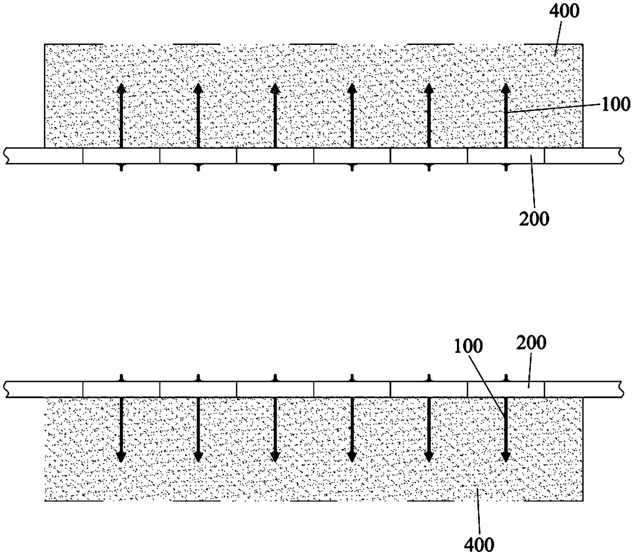
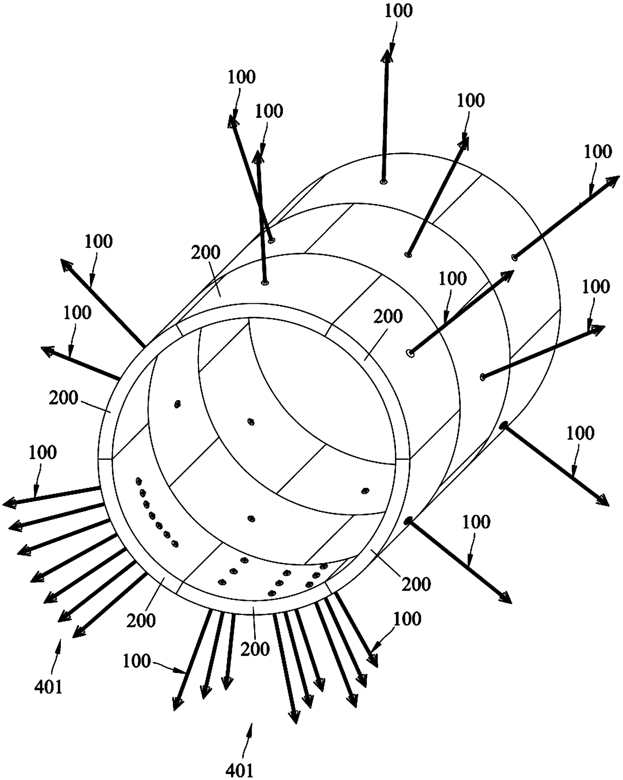
Technical field [0001] The invention relates to the technical field of shield tunnel construction, in particular to a grouting auxiliary mechanism behind the shield tunnel wall and a grouting method. Background technique [0002] In the shield construction process, after the segments of the shield tunnel are assembled, there will generally be a certain gap between the outer wall of the segment and the soil. Generally, the method of grouting behind the wall (or secondary grouting) can be used to Problems such as void filling and controlling ground settlement, but grouting behind the wall will also bring new problems. The reason is that under the condition of high grouting pressure, part of the segment ring often undergoes deformation such as floating due to excessive buoyancy (this is almost a common phenomenon in the construction stage of shield tunnels). Excessive floating and deformation will cause many safety problems to the tunnel structure, such as segment cracking, misalig...

Claims


Application Information

Patent Timeline
Patent Type & Authority Applications(China)
IPC IPC(8): E21D11/10E21D11/08E21D20/02E21D21/00E21D20/00
CPCE21D11/08E21D11/10E21D20/003E21D20/02E21D21/0026E21D21/0093Y02E10/20
Inventor 梁禹黄林冲孙鹏飞
Owner SUN YAT SEN UNIV
Learn More