Fabric three-dimensional fixing device and method thereof

A fabric and equipment technology, applied in the field of fabric three-dimensional setting equipment, can solve the problems of rough edges, loose fabric edges, time-consuming and labor-intensive, etc., to save time, improve production efficiency, and reduce costs.

Active Publication Date: 2018-12-18
JIANGNAN UNIV
View PDF10 Cites 1 Cited by
  • Summary
  • Abstract
  • Description
  • Claims
  • Application Information

AI Technical Summary

Problems solved by technology

[0004] In order to solve the problem that the existing fabrics need to be manually cut after the heat setting is completed, it is time-consuming and labor-intensive, and the manual cutting is greatly affected by human factors, which makes the edges of the cut fabric loose, irregular in shape, and Roughness affects the subsequent use. The present invention uses a more convenient and efficient method to realize the heat setting and demoulding treatment of chemical fiber fabrics, and obtain a three-dimensional fabric with tight and smooth edges after demoulding.

Method used


Image

  • Fabric three-dimensional fixing device and method thereof

Examples


Embodiment 1

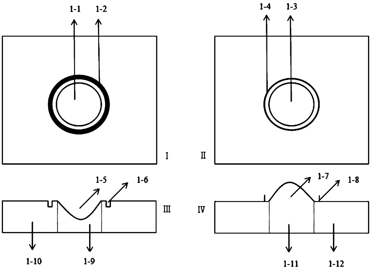
[0032] This embodiment provides a fabric three-dimensional shaping equipment, including an upper mold and a lower mold, see figure 1 , the upper and lower molds respectively include a heat setting zone and a cutting zone; and the working temperature of the cutting zone of the upper and lower molds is higher than the working temperature of the heat setting zone.

[0033] The resistance value of the metal material used in the cutting zone of the upper and lower molds is higher than the resistance value of the metal material used in the heat setting zone of the upper and lower molds.

[0034] The heat-setting zone and the cutting zone of the upper mold are respectively made of metal materials with different resistance values, and the heat-setting zone and the cutting zone of the lower mold are respectively made of metal materials with different resistance values; and the upper The heat setting area of ​​the mold and the heat setting area of ​​the lower mold are made of metal mate...

Embodiment 2

[0046] This embodiment provides a method for three-dimensional shaping of fabrics, the method comprising:

[0047] The fabric to be style-cut is cut into a predetermined size and shape corresponding to the size and shape of the upper and lower moulds.

[0048] Place the cut fabric flat on the surface of the concave part of the lower mould;

[0049] Make the fabric three-dimensional shaping equipment in the working state, the upper mold is lowered until the convex part of the upper mold and the concave part of the lower mold are seamlessly matched;

[0050] Heat setting operation of the fabric through the upper and lower molds;

[0051] After the heat setting operation is completed, the fabric is cut through the upper and lower molds;

[0052] The upper and lower molds are separated to complete the demoulding operation.

[0053] This method can be applied to hernia repair materials.

[0054] Specifically, this embodiment is described by taking the application in hernia repa...


PUM


Abstract

The invention discloses a fabric three-dimensional fixing device and a method thereof, which belong to the technical field of fabric fixing. By using the difference in temperature between different areas of the upper and lower molds in the device, the thermodynamic properties of the fabric are changed, which facilitates subsequent cutting. A cutting device is used again to make the edge of the formed fabric dense and smooth, the molds is smoothly released, so that the manual cutting part is eliminated, the time can be greatly saved, the production efficiency is improved and the cost is reduced; at the same time, the fabric to-be-fixed and cut is pre-cut to a size corresponding to the size of the upper and lower molds, and the raw material can be saved.

Description

technical field [0001] The invention relates to a fabric three-dimensional shaping device and method, belonging to the technical field of textile shaping. Background technique [0002] Fabrics include wovens, knitted fabrics and nonwovens. Woven fabric is a fabric formed by interweaving warp and weft yarns; knitted fabric is divided into weft knitted fabric and warp knitted fabric. Weft knitted fabric is made of one or several yarns along the weft direction. A fabric formed by lapping yarns, while a warp knitted fabric is a fabric formed by lapping yarns along the warp direction of a group of yarns; a nonwoven fabric is a fabric formed by disorderly arrangement of fiber aggregates. With the development of warp knitting technology in recent years, warp knitting products have been more and more widely used in the field of industrial textiles. Warp knitted fabrics are widely used in construction, packaging, transportation, agriculture, fishery, sports, biomedicine, aerospace ...

Claims


Application Information

Patent Timeline
IPC IPC(8): D06C7/02D06H7/00
CPCD06C7/02D06H7/00
Inventor 马丕波徐婉丽蒋高明缪旭红万爱兰陈晴
Owner JIANGNAN UNIV
Why Eureka
Try Eureka