A kind of film-forming equipment and in-situ cleaning method thereof
An in-situ cleaning and film-forming equipment technology, which is applied in the direction of metal material coating process, coating, gaseous chemical plating, etc., can solve the problems of wasting manpower, financial resources, time, and loss, so as to reduce work intensity and avoid particles problems, the effect of shortening the cleaning time
- Summary
- Abstract
- Description
- Claims
- Application Information
AI Technical Summary
Problems solved by technology
Method used
Image

Examples
Embodiment 1
[0055] When the film-forming source is trimethylaluminum, it is used for Al 2 o 3 During film formation, and when cleaning gas is HCl, the cleaning process of a kind of film formation equipment is as follows:
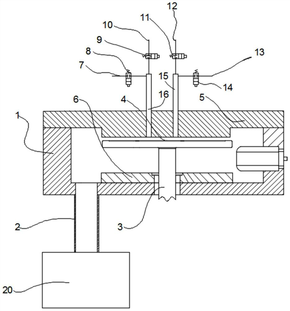
[0056] S01: The cleaning control module opens the valve A (8), nitrogen enters the reaction chamber for purging for 5 minutes, and the flow rate is 2000 sccm.
[0057] S02: The cleaning control module closes valve A (8) and stops purging. The dry pump evacuates the reaction chamber (1) and the vacuum exhaust line (2) for one hour. Set the pressure in the reaction chamber (1) to 2mtorr-10000mtorr, preferably 1000mtorr, and set the cleaning temperature in the reaction chamber (1) to 50-180°C, preferably 130°C.
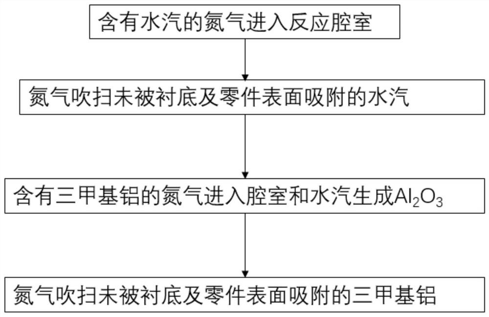
[0058] S03: The cleaning control module opens the valve B (9), nitrogen (10) containing water vapor enters the reaction chamber (1), the ventilation time is 0.1-50 sec, preferably 2 sec, and the flow rate is 100-2000 sccm, preferably 1000 sccm. The water vapor...
Embodiment 2
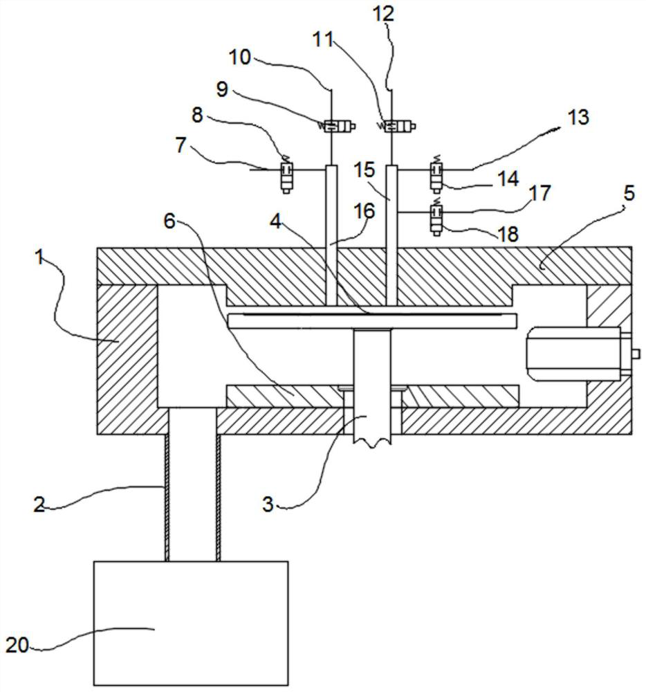
[0063] When the film-forming source is trimethylaluminum, it is used for Al 2 o 3 During film formation, and when cleaning gas is HBr, the cleaning process of a kind of film formation equipment is as follows:
[0064] S01: The cleaning control module opens valve A (8), and nitrogen gas (7) enters the reaction chamber for purging for 5 minutes with a flow rate of 2000 sccm.
[0065] S02: The cleaning control module closes valve A (8) and stops purging. The dry pump evacuates the reaction chamber (1) and the vacuum exhaust line (2) for one hour. Set the pressure of the reaction chamber (1) to 2mtorr-10000mtorr, preferably 1000mtorr, and set the cleaning temperature in the reaction chamber (1) to 265-350°C, preferably 280°C.
[0066] S03: The cleaning control module opens the valve B (9), and the nitrogen gas (10) containing water vapor enters the reaction chamber (1), the ventilation time is 0.1-50 sec, preferably 2 sec, and the flow rate is 100-2000 sccm, preferably 1000 scc...
Embodiment 3
[0071] When the film-forming source is trimethylaluminum, it is used for Al 2 o 3 When forming a film, and the cleaning gas is BCl 3 , an in-situ-cleaned Al 2 O The cleaning process of the film forming equipment is as follows:
[0072] S01: The cleaning control module opens valve A (8), and nitrogen gas (7) enters the reaction chamber for purging for 5 minutes with a flow rate of 2000 sccm.
[0073] S02: The cleaning control module closes valve A (8) and stops purging. Close all intake valves, and dry the pump to evacuate the reaction chamber (1) and the vacuum exhaust line (2) for one hour. Set the pressure of the reaction chamber (1) to 2mtorr-10000mtorr, preferably 1000mtorr, and set the cleaning temperature in the reaction chamber (1) to 265-350°C, preferably 280°C.
[0074] S03: The cleaning control module opens the valve B (9), and the nitrogen gas containing water vapor enters the reaction chamber (1), the ventilation time is 0.1-50 sec, preferably 2 sec, and the f...
PUM
 Abstract
Description
Claims
Application Information
 - Generate Ideas
- Intellectual Property
- Life Sciences
- Materials
- Tech Scout
- Unparalleled Data Quality
- Higher Quality Content
- 60% Fewer Hallucinations
Browse by: Latest US Patents, China's latest patents, Technical Efficacy Thesaurus, Application Domain, Technology Topic, Popular Technical Reports.
© 2025 PatSnap. All rights reserved.Legal|Privacy policy|Modern Slavery Act Transparency Statement|Sitemap|About US| Contact US: help@patsnap.com