3D glass ink spraying device and spraying method

A spraying device and glass technology, applied in the direction of coating, etc., can solve the problems of low spraying efficiency and cumbersome process

Active Publication Date: 2018-12-18
抚州联创恒泰光电有限公司
View PDF7 Cites 2 Cited by
  • Summary
  • Abstract
  • Description
  • Claims
  • Application Information

AI Technical Summary

Problems solved by technology

[0005] Based on this, the purpose of the present invention is to solve the problem that in the prior art, in the existing ink process on 3D glass, it is necessary to carry out the film tearing process, and the process is relatively cumbersome, which leads to the problem of low spraying efficiency

Method used


Image

  • 3D glass ink spraying device and spraying method
  • 3D glass ink spraying device and spraying method
  • 3D glass ink spraying device and spraying method

Examples


Embodiment 1

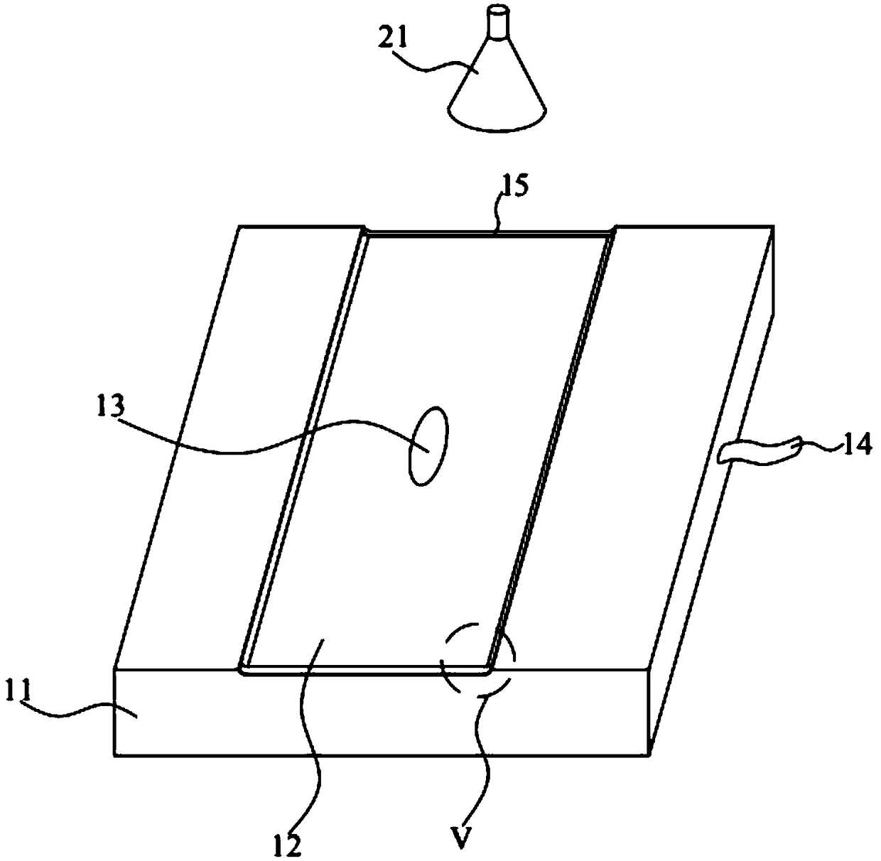
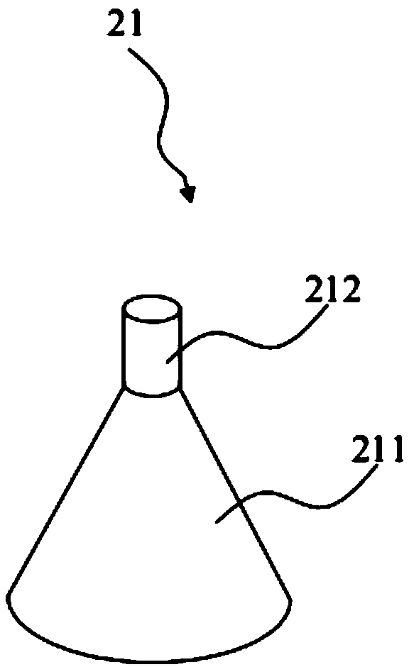
[0036] In order to solve this technical problem, the present invention proposes an ink spraying device for 3D glass, please refer to Figure 1 to Figure 5 , the 3D glass ink spraying device proposed in the first embodiment of the present invention includes a hollow box 11 and a suction cup 21 .

[0037] From figure 1 It can be seen from the figure that a storage tank 12 for fixedly placing 3D glass is provided on the top of the hollow box 11, and a negative pressure through hole 13 is also provided on the top surface of the hollow box 11, and the negative pressure through hole 13 is set In the area where the storage tank 12 is located.

[0038] In order to form a negative pressure in the above-mentioned hollow box 11, in this embodiment, a negative pressure conduit 14 is provided on one side of the hollow box 11, and the negative pressure conduit 14 is connected with the above-mentioned hollow box 11, One end of the negative pressure conduit 14 is connected to a suction moto...

Embodiment 2

[0046] The present invention also proposes an ink spraying method for 3D glass, wherein, please refer to Figure 6 , using the above ink spraying device to spray 3D glass, the method includes the following steps:

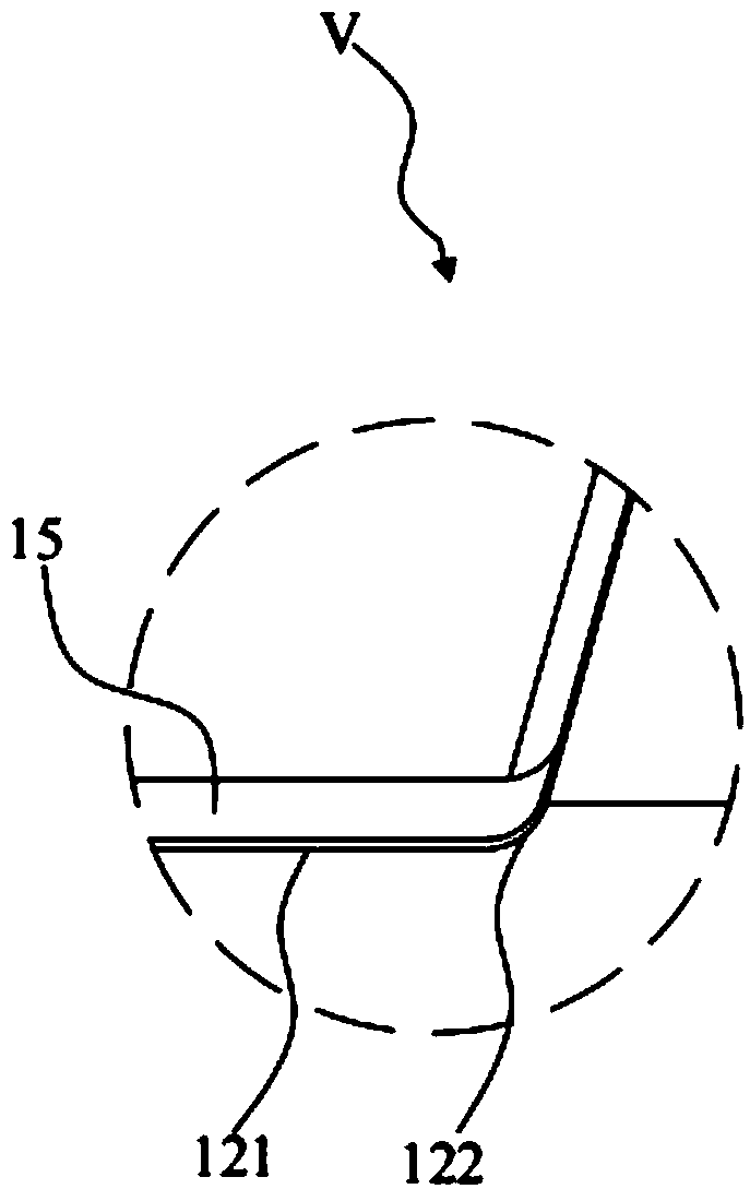
[0047] S101, place the 3D glass in the storage slot on the hollow box, and absorb the air in the hollow box through the negative pressure conduit, so that the 3D glass and the storage slot are closely attached.

[0048] In this step, it should be pointed out that when placing the 3D glass in the storage tank, it is necessary to ensure that the above-mentioned glass flat part 31 corresponds to the position of the straight part 121 of the groove surface, and the glass curved part 32 corresponds to the position of the curved part of the groove surface. 122 is correspondingly attached, and the portion 322 to be sprayed on the 3D glass 30 is positioned at the outside of the storage tank 12 (see figure 2 and Figure 5 ). Then the air in the hollow box is absorbed thro...


PUM


Abstract

The invention discloses a 3D glass ink spraying device and a spraying method. The spraying device comprises a hollow box and a suction cup. The top part of the hollow box is provided with a receivinggroove for fixedly placing the 3D glass. The top surface of the hollow box is provided with a negative pressure through hole. The negative pressure through hole is provided in the area wherein which the receiving groove is located. The hollow box is connected to the negative pressure guide pipethrough hole. The negative pressure though holeguide pipe is used for forming a negative pressure in thehollow box, so as to suckadsorb the 3D glass on the receiving groove. The suction cup is used for suckingadsorbing the 3D glass up after completing a spraying operation. A to-be-sprayed area of the 3Dglass is located at the outside of the receiving groove.While the 3D glass ink spraying device provided by the invention actually sprays, no film sticking process is required, spray technology is simplified, and the spraying efficiency is improved.

Description

technical field [0001] The invention relates to the technical field of spraying technology, in particular to an ink spraying device and a spraying method for 3D glass. Background technique [0002] In recent years, with the continuous development and progress of technology, various mobile terminals have become more and more common in people's daily life. For example, smartphones, smart watches, tablets, wearable smart products, dashboards, and more. [0003] For the above-mentioned various mobile terminal products, 3D glass is an essential and important accessory. In order to ensure the normal display effect of the product, all 3D glass needs to be treated with ink. Traditional 3D glass ink mainly includes two processes: (1) One is the bonding process: the required ink is printed on the film in advance, and then the printed film is bonded to the 3D glass by OCA bonding. (2) One is the spraying process: use a spraying machine to spray ink on the entire concave surface of t...

Claims


Application Information

Patent Timeline
Patent Type & Authority Applications(China)
IPC IPC(8): C03C17/00
CPCC03C17/002C03C2218/112
Inventor 郭书召
Owner 抚州联创恒泰光电有限公司
Why Eureka
Try Eureka