Metal surface treatment process

A metal surface treatment and process technology, applied in metal processing equipment, metal processing machinery parts, manufacturing tools, etc., can solve problems such as affecting the preparation quality of metal plates, affecting the production and processing efficiency of metal plates, and inconvenience for adjusting the rotation direction of the drill bit. , to achieve the effect of simple and convenient punching steps, simple and convenient adjustment steps, and reduced manual operation steps.

Inactive Publication Date: 2018-12-18
佛山诗勤智能科技有限公司
View PDF0 Cites 0 Cited by
  • Summary
  • Abstract
  • Description
  • Claims
  • Application Information

AI Technical Summary

Problems solved by technology

[0002] During the production and processing of sheet metal, the drilling of traditional sheet metal mainly relies on manual adjustment and replacement of the drill bit, which is less efficient. When the drill bit needs to be replaced repeatedly, it needs to be disassembled repeatedly, which greatly affects the quality and speed of the sheet metal preparation, and the traditional The drilling equipment is inconvenient to adjust the rotation direction of the drill bit. Therefore, the drilling has strong limitations and is inconvenient to use, which affects the production and processing efficiency of the metal sheet and needs to be improved.

Method used


Image

  • Metal surface treatment process
  • Metal surface treatment process
  • Metal surface treatment process

Examples


Embodiment Construction

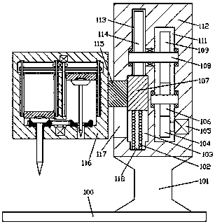
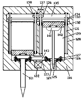
[0013] Combine below Figure 1-3 The present invention will be described in detail.

[0014] refer to Figure 1-3 , a metal surface treatment process according to an embodiment of the present invention, comprising a bottom plate 100, a cylinder 101 is fixed on the top end surface of the bottom plate 100, a mounting seat 112 is fixed on the top end surface of the cylinder 101, and the mounting seat The left end of 112 is provided with a work frame body 116, and the first perforation 124 is symmetrically arranged in the bottom end surface of the work frame body 116, and the inner top wall of the first perforation 124 is provided with an adjustment cavity 129 extending up and down. The bottom wall of the cavity 129 is rotated and fitted with a bevel gear frame 126, and the outer circumference of the bevel gear frame 126 is fixed with an external gear ring 127, and the inside of the bevel gear frame 126 is provided with a second hole opposite to the first through hole 124. Perfo...


PUM


Abstract

The invention discloses a metal surface treatment process which comprises a bottom board. A column is fixedly arranged on the top end face of the bottom board. An installation seat is fixedly arrangedon the top end face of the column. A working frame is arranged at the left side end of the installation seat. First penetrating holes are bilaterally symmetrically formed in the bottom end face of the working frame. Adjustment cavities extending up and down are formed in the inner top walls of the first penetrating holes. Conic tooth frames are installed on the bottom walls of the adjustment cavities in a running fit mode. Outer gear rings are fixedly arranged on the peripheries of the conic tooth frames. Second penetrating holes opposite to the first penetrating holes are formed in the conictooth frames in an up-down run-through mode. Adjustment frames are installed in the adjustment cavities in a sliding fit mode. Bevel gears used for being engaged with the conic tooth frames are installed at the bottom ends of the adjustment frames in a running fit mode. Drill bits are fixedly installed on the bottom end faces of the bevel gears and extend into the second penetrating holes and thefirst penetrating holes. A through cavity is formed between the bottom ends of the adjustment cavities in the left side and the right side in a communicating mode.

Description

technical field [0001] The invention relates to the technical field of sheet metal processing, in particular to a metal surface treatment process. Background technique [0002] During the production and processing of sheet metal, the drilling of traditional sheet metal mainly relies on manual adjustment and replacement of the drill bit, which is less efficient. When the drill bit needs to be replaced repeatedly, it needs to be disassembled repeatedly, which greatly affects the quality and speed of the sheet metal preparation, and the traditional The punching equipment is inconvenient to adjust the rotation direction of the drill bit. Therefore, the punching has strong limitations and is inconvenient to use, which affects the production and processing efficiency of the metal sheet and needs to be improved. Contents of the invention [0003] The object of the present invention is to provide a metal surface treatment process for overcoming the above-mentioned defects in the p...

Claims


Application Information

Patent Timeline
Patent Type & Authority Applications(China)
IPC IPC(8): B23Q1/44B23Q5/04B23Q5/28B23Q5/38
CPCB23Q1/44B23Q5/04B23Q5/28B23Q5/38
Inventor 钟锦桃
Owner 佛山诗勤智能科技有限公司
Why Eureka
Try Eureka