
Punching machine

A punching machine and punching technology, applied in the direction of metal processing equipment, forming tools, manufacturing tools, etc., can solve the problems of uneven force on the workpiece, affecting the stability of punching, and easy vibration, so as to reduce deformation and improve Punching stability, effect of preventing mutual misalignment

Active Publication Date: 2017-05-31
新昌县长城空调部件股份有限公司
View PDF12 Cites 0 Cited by
  • Summary
  • Abstract
  • Description
  • Claims
  • Application Information

AI Technical Summary

Problems solved by technology

However, during the punching process of the punching machine, there is no guiding part, which is prone to vibration, thereby affecting the punching stability, and the force on the workpiece is not uniform

Method used


Image

  • Punching machine
  • Punching machine
  • Punching machine

Examples


Embodiment Construction

[0018] In order to make the above objects, features and advantages of the present invention more comprehensible, specific implementations of the present invention will be described in detail below in conjunction with the accompanying drawings. In the following description, numerous specific details are set forth in order to provide a thorough understanding of the present invention. However, the present invention can be implemented in many other ways different from those described here, and those skilled in the art can make similar improvements without departing from the connotation of the present invention, so the present invention is not limited by the specific implementations disclosed below.

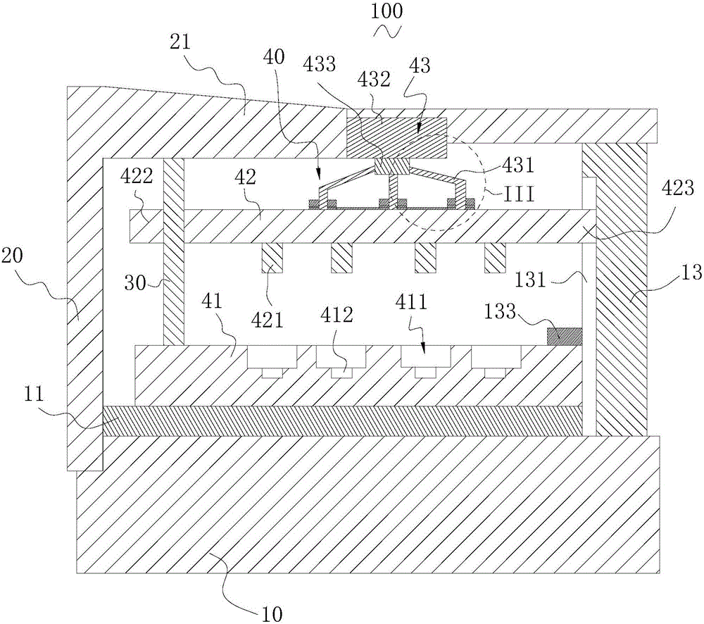
[0019] The invention relates to a punching machine. The punching machine includes a base, a support seat, a guide rod and a punching assembly, a workbench is arranged on the base, the support seat is arranged on one side of the base, a support portion is formed on the top of the suppo...


PUM

PropertyMeasurementUnit
heightaaaaaaaaaa
thicknessaaaaaaaaaa
thicknessaaaaaaaaaa

Abstract

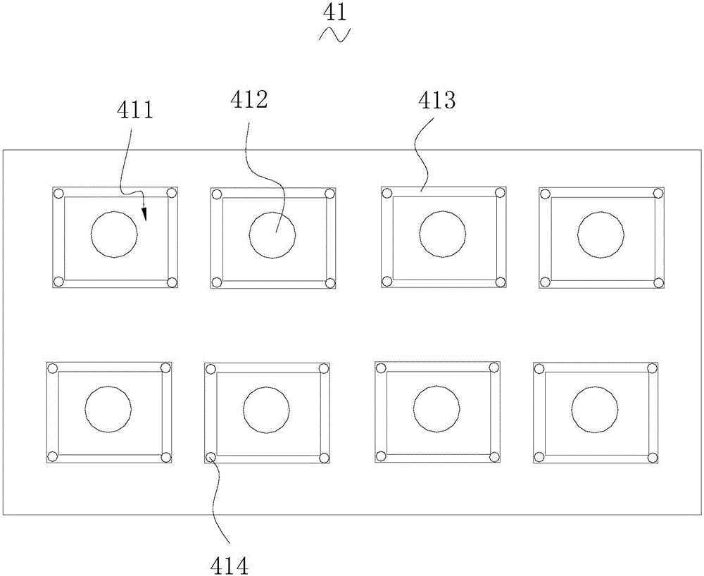
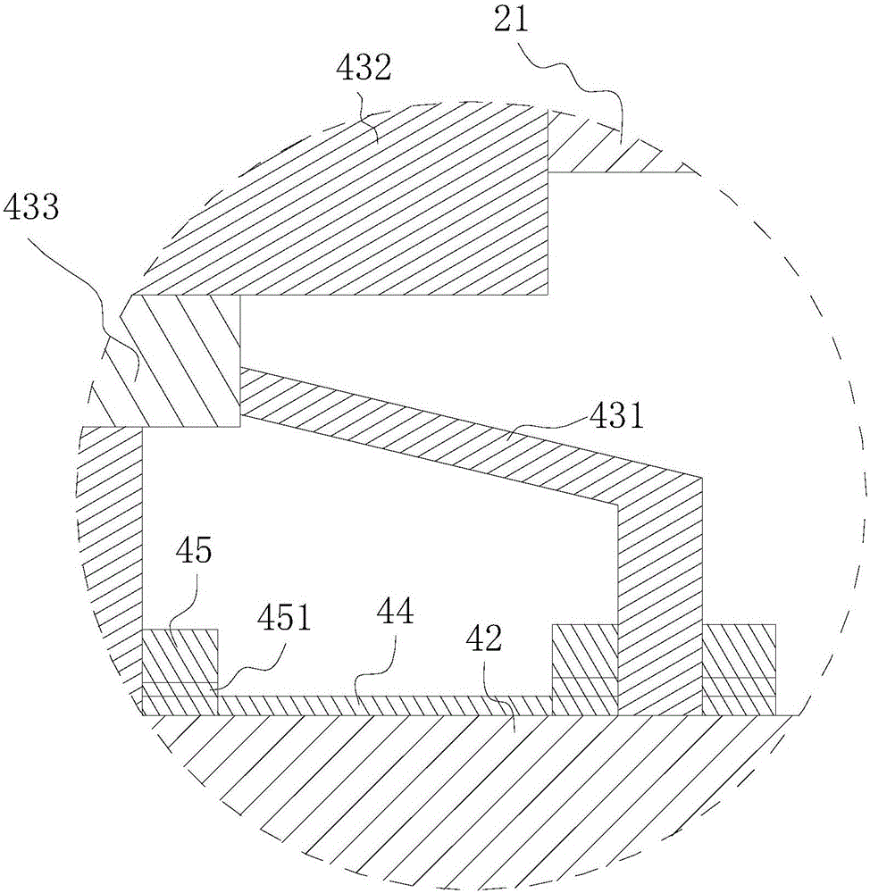
The invention relates to a punching machine. The punching machine comprises a base, a support seat, a guiding bar and a punching assembly; the base is provided with a work bench; a support part is formed on the top of the support seat; the punching assembly comprises a first die holder, a second die holder and a driving member, wherein the first die holder is installed on the work bench and the driving member comprises multiple driving parts; the multiple driving parts are arranged with intervals and are connected to the second die holder. The first die holder is provided with a receiving groove; the receiving groove is provided with a pressure sensor; the pressure sensor is electrically connected with the driving member; the driving member is provided with a socket board; the socket board is provided with multiple socket holes; the multiple driving parts are installed in the socket holes in a penetrating mode; the socket board is provided with multiple shield and sustain rings which sleeve on the multiple driving parts. The punching process of the punching machine is stable and the stress on workpieces is uniform.

Description

technical field [0001] The invention relates to a punching machine. Background technique [0002] In industrial production, it is often necessary to punch workpieces. And in order to realize above-mentioned punching operation, need to adopt punching machine to realize. The punching machine generally includes a base, a support seat, a guide rod and a punching assembly, a worktable is arranged on the base, the support seat is arranged on the workbench, the guide rod is arranged adjacent to the support seat, The punching assembly includes a first mold base, a second mold base and a driving member, the first mold base is arranged on the workbench, the driving member is arranged on the support seat, and the second mold holder The seat is connected to the driving part and sheathed on the guide rod. However, during the punching process of the punching machine, there is no guiding component, and vibration is easily generated, thereby affecting punching stability, and the force on...

Claims


Application Information

Patent Timeline
Patent Type & Authority Applications(China)
IPC IPC(8): B21D28/24B21D37/16B21D37/18
CPCB21D28/24B21D37/16B21D37/18
Inventor 黄巧玲
Owner 新昌县长城空调部件股份有限公司
Learn More