A stamping die clamping device with angle adjustment function
What is Al technical title?
Al technical title is built by PatSnap Al team. It summarizes the technical point description of the patent document.
A stamping die and angle adjustment technology, applied in forming tools, manufacturing tools, safety equipment, etc., can solve the problems of low work efficiency, weak practicability, and inability to adjust the angle of the die, and achieve the effect of improving work efficiency and fast fixing
Active Publication Date: 2020-03-27
安庆牛力模具股份有限公司
View PDF5 Cites 0 Cited by
Summary
Abstract
Description
Claims
Application Information
AI Technical Summary
This helps you quickly interpret patents by identifying the three key elements:
Problems solved by technology
Method used
Benefits of technology
Problems solved by technology
[0003] The clamping devices of most stamping dies cannot quickly fix the mold, and at the same time cannot adjust the mold horizontally. The error during fixation causes the situation that the clamping cannot be performed, resulting in low work efficiency, and cannot be clamped during clamping. Adjust the angle of the mold, and at the same time, manual adjustment will cause a waste of time, and manual adjustment will easily cause dangerous situations. In the prior art, the operation is complicated, the practicability is weak, and it is not easy to popularize and use. Therefore, we propose a method with an angle The stamping die clamping device with adjustable function is used to solve the above problems
Method used
Image
Click on the blue label to locate the original text in one second.
Reading with bidirectional positioning of images and text.
Examples
Embodiment Construction
[0017] The technical solutions in the embodiments of the present invention will be clearly and completely described below in conjunction with the accompanying drawings in the embodiments of the present invention. Obviously, the described embodiments are only a part of the embodiments of the present invention, rather than all the embodiments. Based on the embodiments of the present invention, all other embodiments obtained by those of ordinary skill in the art without creative work shall fall within the protection scope of the present invention.
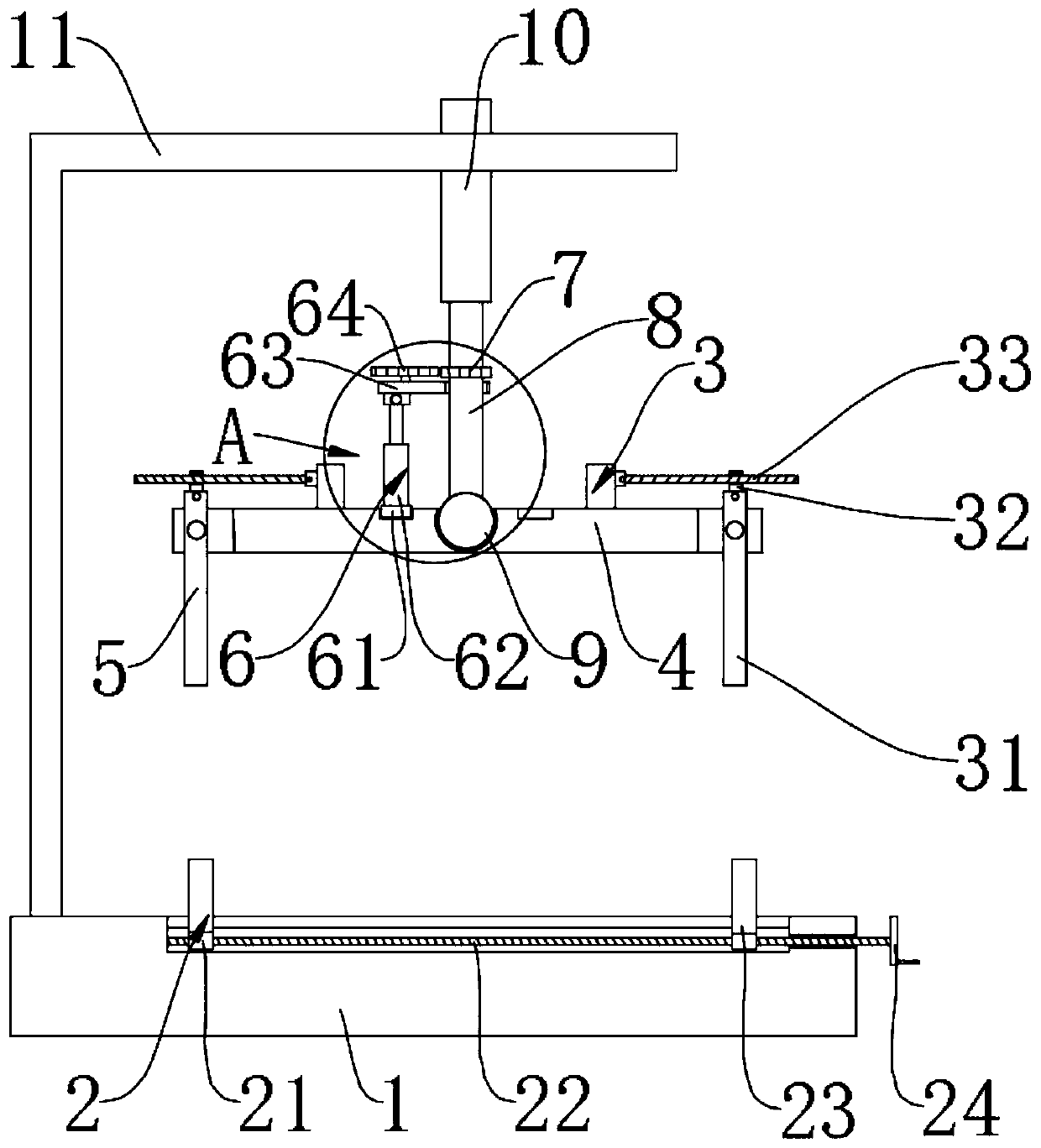
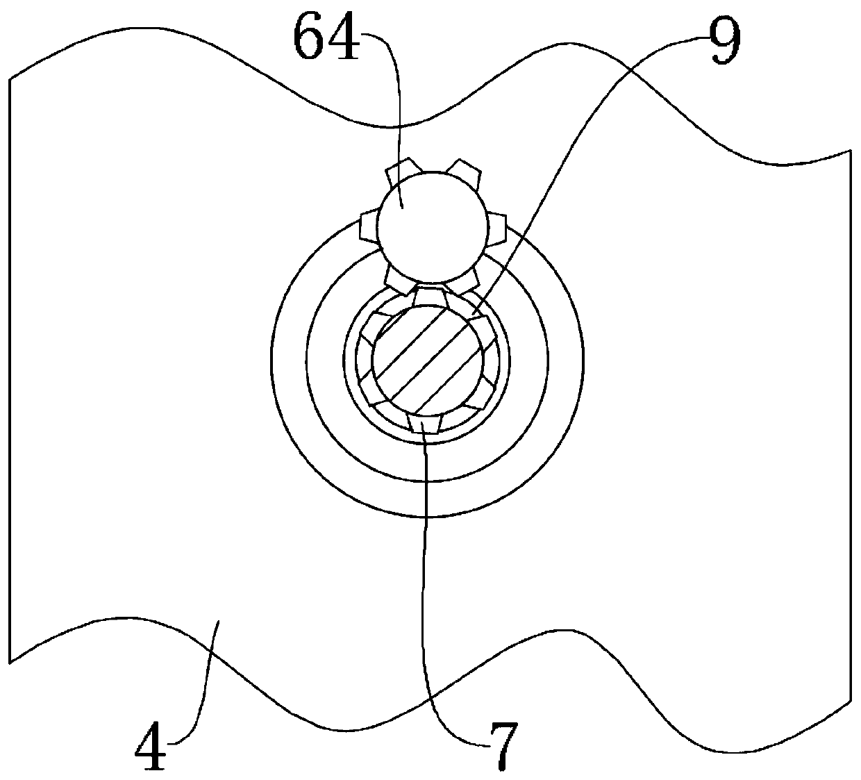
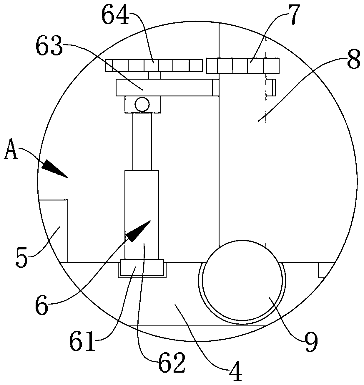
[0018] See Figure 1-3 , The present invention provides a technical solution: a stamping die clamping device with angle adjustment function, comprising a base 1, a clamping device 2 is provided on the base 1, and the clamping device 2 includes a first fixing block 21 and a screw rod 22. The second fixing block 23 and the rocking handle 24, the first fixing block 21 is provided with a screw rod 22, the other end of the screw rod 22 is pen...
PUM
Abstract
The invention discloses a stamping die clamping device with the angle adjusting function. The device comprises a base, a clamping device body is arranged on the base, a first limiting device is arranged above the clamping device body, and is rotatably arranged on a fixed base, one end of the fixed base is rotatably provided with a second limiting device, a rotating device is arranged on one side of the second limiting device, and comprises a sliding block, an air cylinder, a limiting block and a gear, the air cylinder is fixedly arranged on the sliding block, the limiting block is fixedly arranged on the upper end of the air cylinder, the gear is rotatably arranged on the limiting block, a die can be rapidly fixed, meanwhile, the die can be transversely adjusted, the condition that duringfixing, due to errors, the clamping cannot be achieved is avoided, work efficiency is improved, the angle adjusting of the die can be quickened, meanwhile, time waste due to manual adjusting can be avoided, the dangerous condition caused by manual adjusting is avoided, and the device is easy to operate, high in practicability and convenient to use and popularize.
Description
Technical field [0001] The invention relates to the technical field of mold manufacturing equipment, in particular to a stamping mold clamping device with an angle adjustment function. Background technique [0002] Molds, various molds and tools used in industrial production to obtain the required products by methods such as injection molding, blow molding, extrusion, die-casting or forging molding, smelting, and stamping. In short, a mold is a tool used to make molded objects. This tool is composed of various parts, and different molds are composed of different parts. It mainly realizes the processing of the shape of the article by changing the physical state of the formed material. Known as the "Mother of Industry". [0003] Most of the clamping devices of stamping dies cannot quickly fix the mold, and at the same time, cannot adjust the mold laterally. The error in the fixing causes the situation that the clamping cannot be carried out, which causes the work efficiency to be t...
Claims
Application Information
Patent Timeline
Application Date:The date an application was filed.
Publication Date:The date a patent or application was officially published.
First Publication Date:The earliest publication date of a patent with the same application number.
Issue Date:Publication date of the patent grant document.
PCT Entry Date:The Entry date of PCT National Phase.
Estimated Expiry Date:The statutory expiry date of a patent right according to the Patent Law, and it is the longest term of protection that the patent right can achieve without the termination of the patent right due to other reasons(Term extension factor has been taken into account ).
Invalid Date:Actual expiry date is based on effective date or publication date of legal transaction data of invalid patent.