
A wireless electric energy transmission system and method capable of identifying mutual inductance and load from a primary side

A technology of wireless power transmission and primary side, which is applied in the direction of control/regulation system, electrical components, and adjustment of electrical variables, etc. It can solve the problems of reducing system complexity, enhancing robustness, and reducing costs, so as to improve transmission stability, The effect of reducing system complexity and improving transmission efficiency

Inactive Publication Date: 2018-12-14
SOUTHWEST JIAOTONG UNIV
View PDF4 Cites 13 Cited by
  • Summary
  • Abstract
  • Description
  • Claims
  • Application Information

AI Technical Summary

Problems solved by technology

[0003] The purpose of the present invention is: in order to solve the problem that the wireless power transmission system in the prior art is equipped with complex redundant equipment at both ends of the primary side and the secondary side, resulting in high cost, complicated circuit and poor reliability, the present invention proposes a The wireless power transmission system that identifies the mutual inductance and load from the original side does not require additional devices. Only by detecting the voltage and current signals at the transmitting end in real time to identify the dynamic change of the mutual inductance or load impedance at the pickup end, which can effectively reduce system complexity and enhance robustness. Rod, lower cost

Method used


Image

  • A wireless electric energy transmission system and method capable of identifying mutual inductance and load from a primary side
  • A wireless electric energy transmission system and method capable of identifying mutual inductance and load from a primary side
  • A wireless electric energy transmission system and method capable of identifying mutual inductance and load from a primary side

Examples


Embodiment Construction

[0060] In order to make the object, technical solution and advantages of the present invention clearer, the present invention will be further described in detail below in conjunction with the accompanying drawings and embodiments. It should be understood that the specific embodiments described here are only used to explain the present invention, and are not intended to limit the present invention, that is, the described embodiments are only some of the embodiments of the present invention, but not all of the embodiments. The components of the embodiments of the invention generally described and illustrated in the figures herein may be arranged and designed in a variety of different configurations.

[0061] Accordingly, the following detailed description of the embodiments of the invention provided in the accompanying drawings is not intended to limit the scope of the claimed invention, but merely represents selected embodiments of the invention. Based on the embodiments of the...


PUM


Abstract

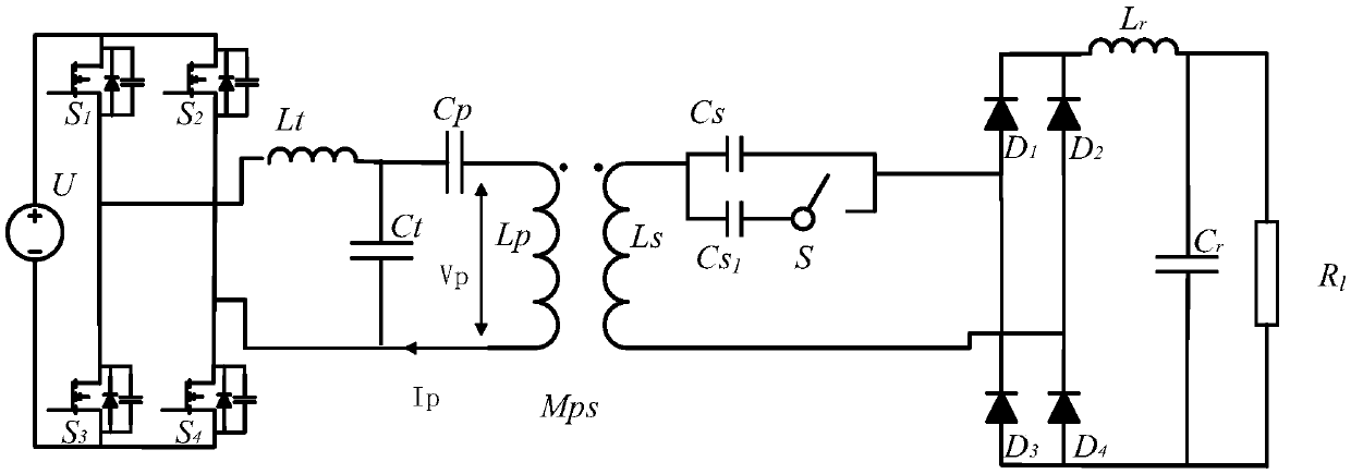
The invention discloses a wireless electric energy transmission system and method capable of identifying mutual inductance and load from a primary side, relates ot the field of wireless electric energy transmission, and is used for solving the problem that a wireless electric energy transmission system in the prior art is provided with complex redundant equipment at two ends of the primary side and the secondary side, resulting in the problems of high cost, complex circuit, and poor reliability. The wireless electric energy transmission system comprises a DC power supply, a high frequency inverter circuit, a primary side compensation circuit, a transceiver coil, a secondary compensation circuit, a high frequency rectifier circuit, a filter circuit and a load, the secondary side is composedof a coupling structure based on a series compensation equivalent circuit, the primary side coupling compensation structure is not limited, the secondary side coupling compensation structure includesan inductor LS and a capacitor CS connected in series in sequence, in the secondary side compensation circuit, a capacitor CS1 branch circuit with a bidirectional switch is connected in parallel between two ends of the capacitor CS. The wireless electric energy transmission system provided by the invention identifies the dynamic change of mutual inductance or load impedance of the pickup end by detecting the voltage and current signals of the transmitting end in real time, does not need an additional device, and can effectively reduce system complexity and cost.

Description

technical field [0001] The present invention relates to the field of wireless power transmission, in particular to a wireless power transmission system and method capable of identifying mutual inductance and load from the primary side. Background technique [0002] When the wireless power transmission technology is applied to the power supply of rail transit trains, electric vehicles and other mobile devices, it overcomes the defects of the traditional wired power transmission technology, such as easy carbon deposition, contact sparks, troublesome plugging operations, etc., and effectively improves the quality and safety of power supply. Sex and reliability, has a high use value. In the wireless power transmission system, when it is necessary to control the output voltage or output current, there are mainly two ways to control it. One is to use a controller at the transmitter end of the primary side and the pick-up end of the secondary side, and the open loop is used for the...

Claims


Application Information

Patent Timeline
IPC IPC(8): H02M3/335
CPCH02M3/3353
Inventor 李砚玲李晨何正友麦瑞坤
Owner SOUTHWEST JIAOTONG UNIV
Learn More