
Virtual reality-based head-mounted equipment and system thereof

A head-mounted device and virtual reality technology, applied in optical components, optics, instruments, etc., can solve problems such as user discomfort and unsatisfactory visual effects, and achieve the effect of reducing experience, good visual effects, and avoiding discomfort.

Active Publication Date: 2018-12-14
ZHEJIANG NORMAL UNIVERSITY
View PDF7 Cites 13 Cited by
  • Summary
  • Abstract
  • Description
  • Claims
  • Application Information

AI Technical Summary

Problems solved by technology

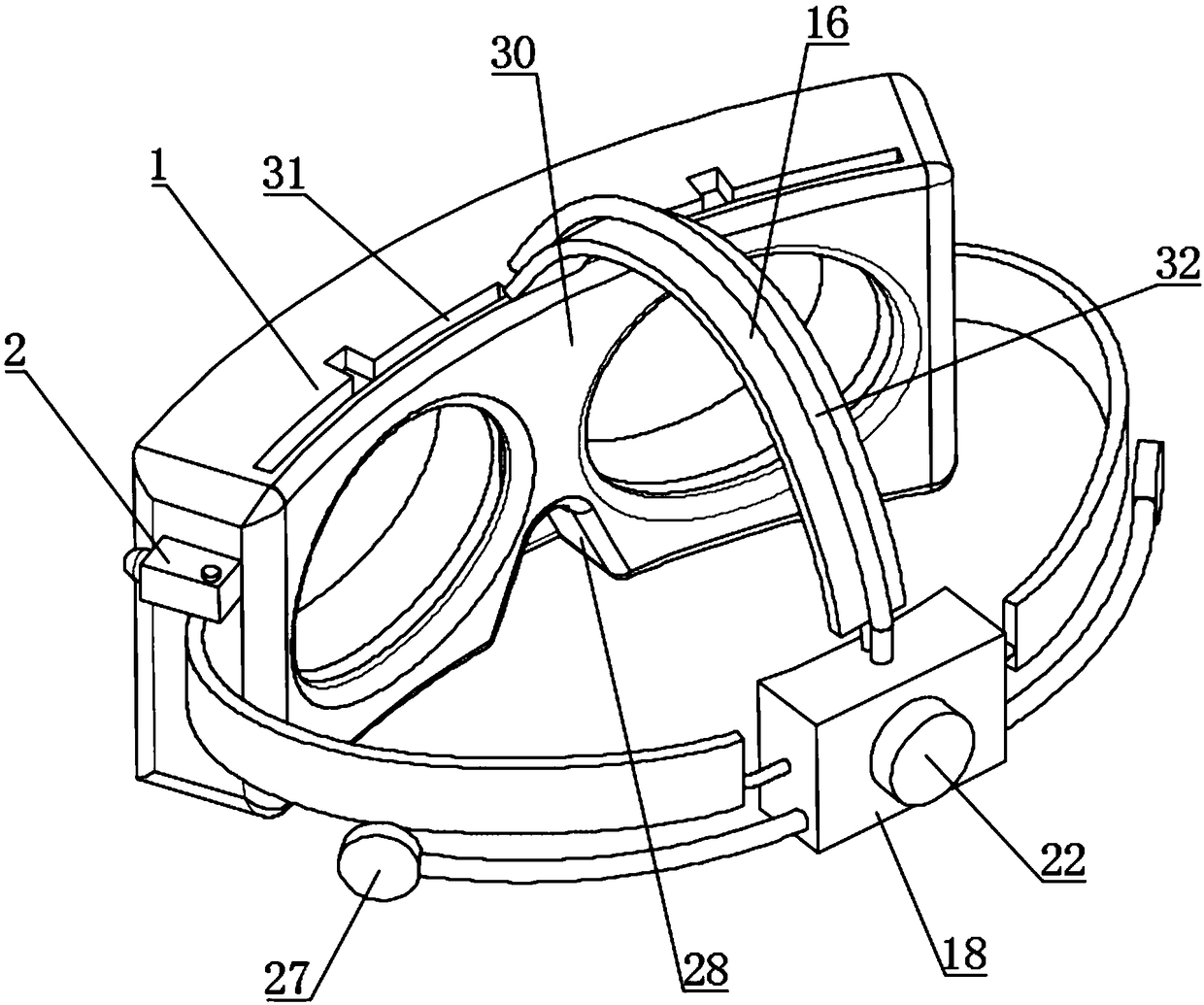
[0002] Virtual reality head-mounted devices are generally called VR glasses, which use head-mounted displays to close people's vision and hearing to the outside world, and guide users to feel like they are in a virtual environment. Head-mounted displays are The earliest virtual reality display, its display principle is that the left and right eye screens display the images of the left and right eyes respectively. After the human eyes obtain this information with differences, they will generate a three-dimensional effect in the mind. As the name suggests, the VR glasses require users to wear them on the eyes. , but now many myopic people are wearing myopia glasses. If the VR glasses are worn outside the myopia glasses, the VR glasses will squeeze the myopia glasses and make the user uncomfortable. If the myopia glasses are taken off and the VR glasses are worn It will lead to unsatisfactory visual effects. At the same time, it is difficult for the current VR glasses to fit the faces of different groups of people, resulting in discomfort for users. To solve the above problems, the present invention provides a head-mounted device and its system based on virtual reality.

Method used


Image

  • Virtual reality-based head-mounted equipment and system thereof
  • Virtual reality-based head-mounted equipment and system thereof
  • Virtual reality-based head-mounted equipment and system thereof

Examples


Embodiment 1

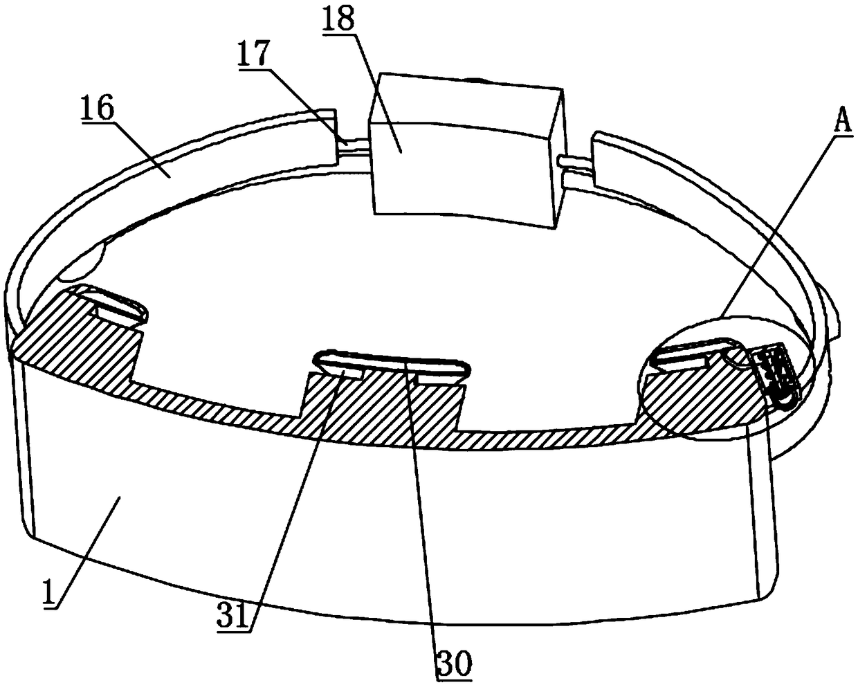
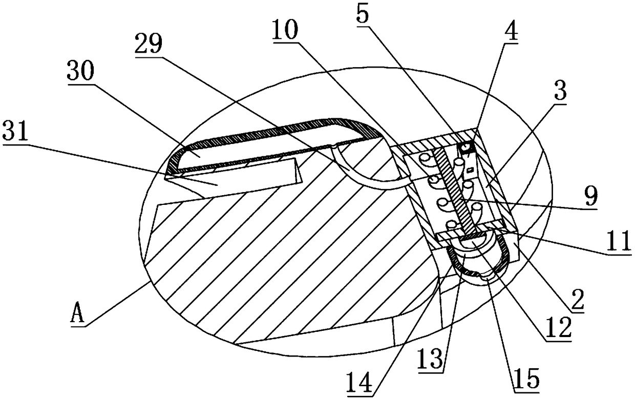
[0028]Embodiment 1, the present invention provides a technical solution: a head-mounted device based on virtual reality and its system, including a main body 1 and a fixed block 18, and the middle part of the lower side of the main body 1 is provided with a relief groove 28, allowing The slot 28 can give way to the nose, thereby making the user more comfortable. The upper side of the main body 1 is provided with two placement slots 31, and the placement slots 31 are equipped with two slot covers, which can cover the placement slots 31 To prevent dust from entering, matching lenses can be placed inside the placement groove 31, so that users can watch clearly without wearing glasses. One side of the main body 1 is fixedly connected with an inflatable block 2. The interior of the inflatable block 2 is provided with an inner chamber 3, and the interior of the inner chamber 3 is provided with a fixed shaft 9 arranged horizontally, one end of the fixed shaft 9 is fixedly connected to...

Embodiment 2

[0030] Embodiment 2, for implementation 1, the lenses placed in the placement groove 31 must be matched. For this situation, it is often impossible to meet the needs of users with different needs for vision correction. If users can wear their own eyes and then If the present invention can be used again, the convenience will be greatly improved. Generally, there are connecting frames and nose pads in the middle of the glasses. If a large space is simply provided for placing the nose pads and connecting frames in order to meet the needs of most glasses, light leakage will be caused. , let the light on both sides cause interference and affect the experience effect, so on the basis of Embodiment 1, a movable baffle 37 is added. Specifically, a dark groove 33 and a chute are provided in the main body 1 and above the relief groove 28 34, the inside of the chute 34 is slidably connected with a first slide bar 35, and the side wall of the dark trough 33 away from the chute 34 is slidab...

Embodiment 3

[0031] Embodiment 3, on the basis of Embodiment 1 or Embodiment 2, the one-way air intake structure in the inflatable block 2 is replaced, and the one-way air intake structure includes a fixed shaft 9 arranged vertically, and the fixed shaft 9. The upper end is slidably connected with the sliding chamber 7 provided in the inner cavity 3, and the lower end is fixedly connected with a rubber pad 11 corresponding to the through hole 13 provided at the bottom of the inflatable block 2. The rubber pad 11 is under the action of gravity under the condition of no air intake. It falls and is compressed under internal pressure, without springs and other components, making production and processing easier and more reliable.

[0032] For Embodiments 1, 2, and 3, the layout and installation of the electronic components are basically the same. The inside of the main body 1 is provided with two screens corresponding to the positions of the two eyes, and the main body 1 is provided with a vide...


PUM


Abstract

The invention discloses virtual reality-based head-mounted equipment and a system thereof. The head-mounted equipment comprises a main body and a fixed block; a yielding groove is formed in the middleof the lower side surface of the main body; and two placement grooves are formed in the upper side surface of the main body. Through cooperation between an inflatable ball and an air vent, air can becontinuously pumped into an airbag by pressing the inflatable ball, so that the airbag can be tightly attached to the faces of different users, and a user feels more comfortable; through cooperationbetween a rotating rod and a partition plate, a connecting rope can be wound on the rotating rod by rotating the rotating rod to change the length of a bandage, so that the equipment is suitable for different people; and matched lenses can be directly inserted into the placement grooves, so that the user can clearly perform watching without wearing glasses, or the equipment is used under the condition of wearing the glasses by adjusting the position of a baffle, and the requirements of different users of the same equipment can be met.

Description

technical field [0001] The invention relates to the technical field of VR equipment, in particular to a virtual reality-based head-mounted equipment and a system thereof. Background technique [0002] Virtual reality head-mounted devices are generally called VR glasses, which use head-mounted displays to close people's vision and hearing to the outside world, and guide users to feel like they are in a virtual environment. Head-mounted displays are The earliest virtual reality display, its display principle is that the left and right eye screens display the images of the left and right eyes respectively. After the human eyes obtain this information with differences, they will generate a three-dimensional effect in the mind. As the name suggests, the VR glasses require users to wear them on the eyes. , but now many myopic people are wearing myopia glasses. If the VR glasses are worn outside the myopia glasses, the VR glasses will squeeze the myopia glasses and make the user un...

Claims


Application Information

Patent Timeline
Patent Type & Authority Applications(China)
IPC IPC(8): G02B27/01
CPCG02B27/0176
Inventor 李斌乾卢佳佳
Owner ZHEJIANG NORMAL UNIVERSITY
Learn More