
Method for temperature compensation of SAR sensor of terminal and terminal

A temperature compensation, sensor technology, applied in the direction of temperature compensation modification, instrumentation, measurement of interference from external sources, etc., can solve problems such as false triggering of SAR sensors

Active Publication Date: 2018-12-14
XIAN YIPU COMM TECH
View PDF6 Cites 4 Cited by
  • Summary
  • Abstract
  • Description
  • Claims
  • Application Information

AI Technical Summary

Problems solved by technology

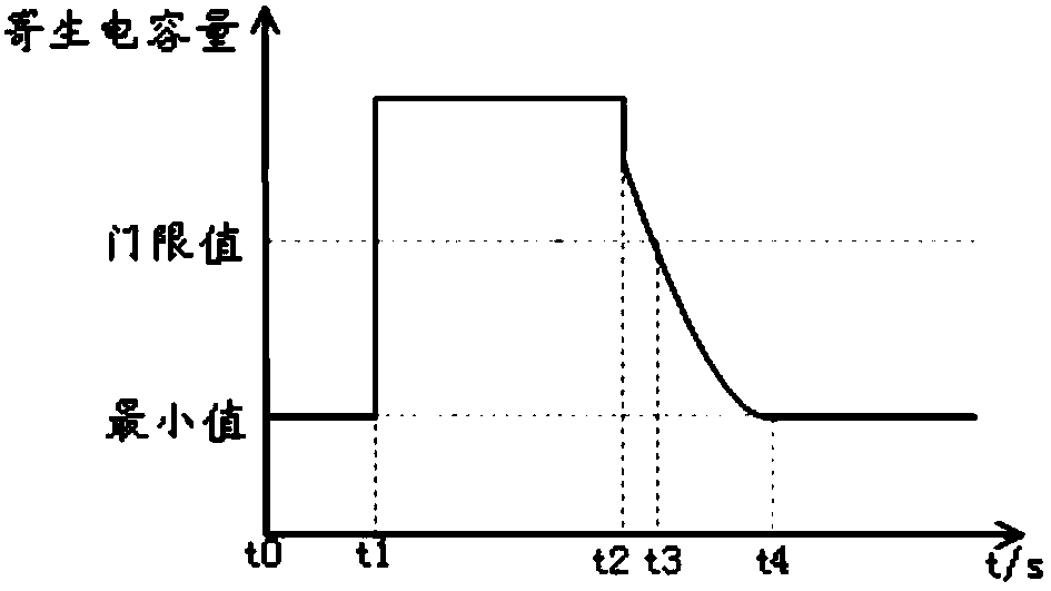
[0003] At present, the SAR sensor in the handheld terminal will introduce a temperature compensation mechanism to achieve a more accurate judgment mechanism. Even so, there are still some problems of false triggering of the SAR sensor caused by inaccurate temperature compensation. In scenes that change rapidly, false triggering of some SAR sensors may occur, such as figure 1 As shown, it is an application scenario where the temperature changes rapidly. Since the parasitic capacitance is the minimum value during the period from t0 to t1, it can be judged that the human body is far away from t0 to t1, and it is detected at point t1 When the human body approaches, the change of the parasitic capacitance exceeds the preset threshold. After a long time of hand-holding from t1 to t2, the temperature of the hand-held terminal reaches about 37°C, and then the human hand leaves the terminal at time t2. At this time, The system should determine that the human body is far away, but because the temperature detection and compensation mechanism of the SAR sensor cannot quickly track the temperature change, the system only determines that the human body is far away at the time point t3. In fact, from the time t2 to t3, the system false trigger

Method used


Image

  • Method for temperature compensation of SAR sensor of terminal and terminal
  • Method for temperature compensation of SAR sensor of terminal and terminal
  • Method for temperature compensation of SAR sensor of terminal and terminal

Examples


Embodiment Construction

[0051] In order to make the object, technical solution and beneficial effects of the present invention more clear, the present invention will be further described in detail below in conjunction with the accompanying drawings and embodiments. It should be understood that the specific embodiments described here are only used to explain the present invention, not to limit the present invention.

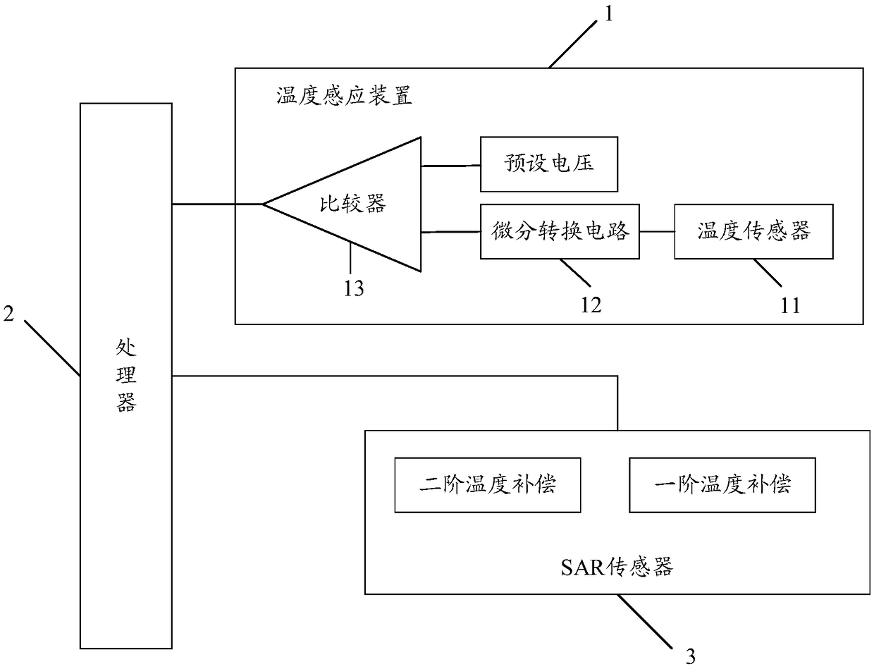
[0052] figure 2 It exemplarily shows a schematic structural diagram of a terminal provided by an embodiment of the present invention, as shown in figure 2 As shown, the terminal may include: a temperature sensing device 1 , a processor 1 and a SAR sensor 3 . in:

[0053] The temperature sensing device 1 is electrically connected to the processor 2, and is configured to send a first trigger signal to the processor 2 when it detects that the temperature variation of the SAR sensor 3 exceeds a preset value.

[0054] The processor 2 is electrically connected to the SAR sensor 3 and conf...


PUM


Abstract

The embodiment of the present invention relates to the technical field of terminals, especially to a method for temperature compensation of an SAR (Specific Absorption Rate) sensor of a terminal and aterminal. The terminal comprises a temperature induction device, a processor and an SAR sensor; the temperature induction device is configured to send first triggering signals to the processor when it is detected that a temperature variable of the SAR sensor exceeds a preset value; the processor is configured to send first temperature control signals to the SAR sensor when the first triggering signals are received; and the SAR sensor is configured to start second-order temperature compensation of the SAR sensor according to the first temperature control signals, wherein the second-order temperature compensation and first-order temperature compensation of the SAR sensor commonly compensate base line data of the SAR sensor. Therefore, the method for temperature compensation of the SAR sensor of the terminal and the terminal can ensure the base data of the SAR sensor, can track the variable of the temperature in real time and can avoid the problem that the false triggering of the SAR sensor is caused by drastic changed temperature of the terminal.

Description

technical field [0001] Embodiments of the present invention relate to the technical field of terminals, and in particular, to a method for performing temperature compensation on a SAR sensor of a terminal and a terminal. Background technique [0002] SAR (Specific Absorption Rate, electromagnetic wave absorption ratio), is the electromagnetic wave energy absorption ratio of mobile phones or wireless products. It is defined as: under the action of an external electromagnetic field, an induced electromagnetic field will be generated in the human body. Radiation is quantified and measured. With the development of mobile communications, handheld mobile terminals are getting closer to people's lives, and people use mobile terminals with increasing frequency and usage time, such as mobile phones and tablets. [0003] At present, the SAR sensor in the handheld terminal will introduce a temperature compensation mechanism to achieve a more accurate judgment mechanism. Even so, there...

Claims


Application Information

Patent Timeline
IPC IPC(8): G01R1/44G01R31/00
CPCG01R1/44G01R31/001G01R29/0814G01R29/0878G01S13/9094
Inventor 李伟
Owner XIAN YIPU COMM TECH
Learn More