Accurate river water quality underwater monitoring device
A monitoring device and water quality monitoring technology, applied in the direction of measuring devices, test water, instruments, etc., can solve the problems of inability to control the cabin, limited steering force of the cabin, and affect the normal driving of the cabin, so as to improve accuracy, facilitate movement, area wide effect
- Summary
- Abstract
- Description
- Claims
- Application Information
AI Technical Summary
Problems solved by technology
Method used
Image
Examples
Embodiment 1
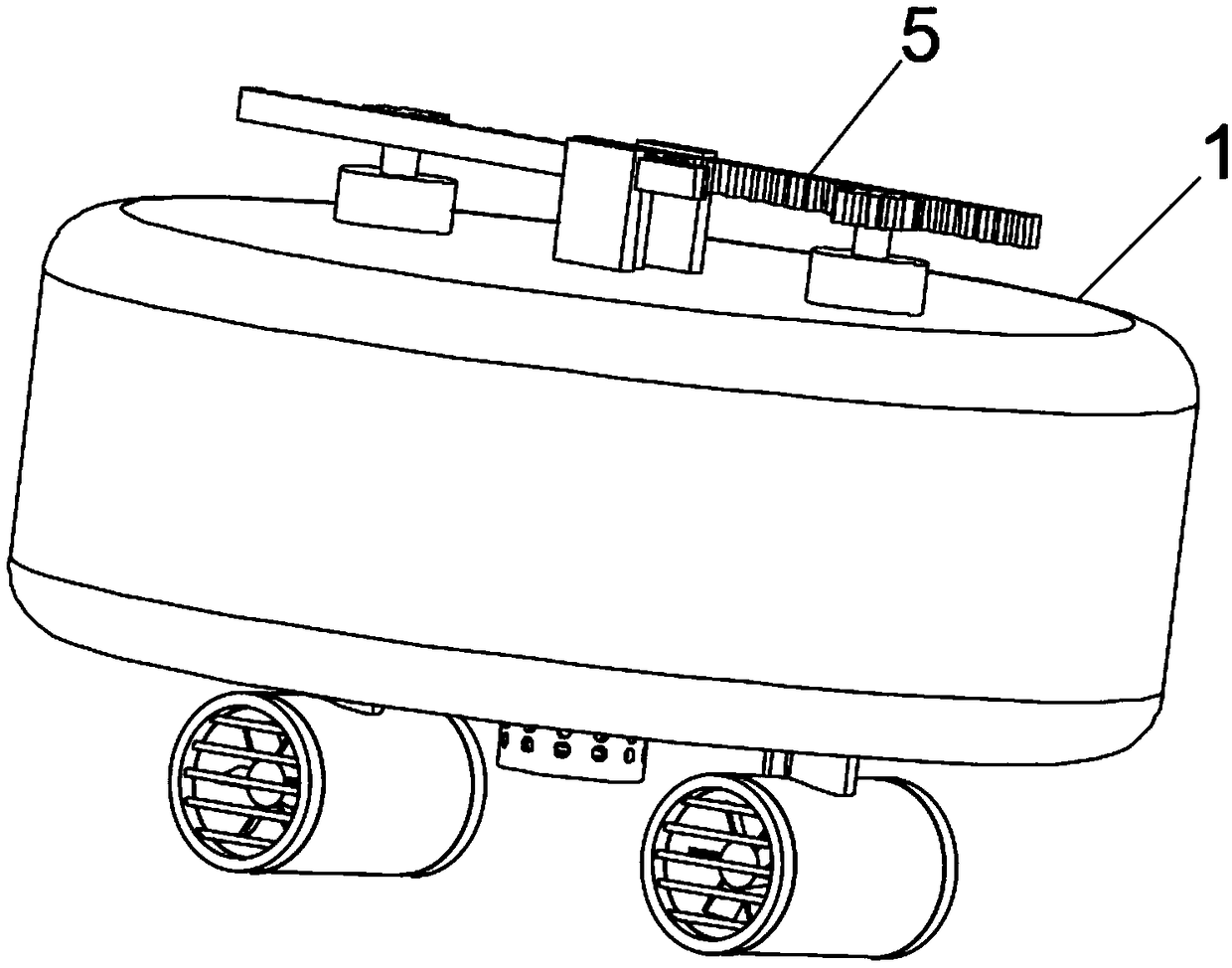
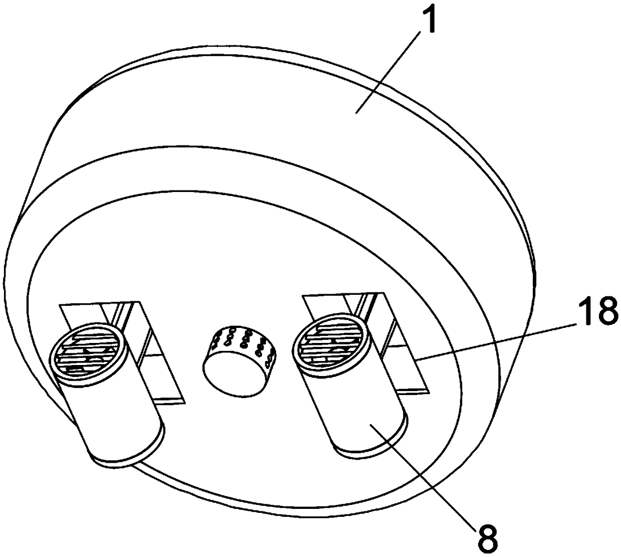
[0052] Embodiment one please refer to Figure 1-4 , the present invention provides a technical solution: a precise river water quality underwater monitoring device, including a buoy 1 and a water quality monitoring head 4, characterized in that: the inside of the buoy 1 is horizontally fixed with a mounting plate 2, and the mounting plate 2 The space in the buoy 1 is divided into two, the space above the mounting plate 2 is the upper cavity 48, the space below the mounting plate 2 is the lower cavity 49, and the control device 3 is fixed in the middle of the top of the mounting plate 2, the control device 3 is located in the upper cavity 48, the control device 3 is electrically connected to the water quality monitoring head 4, and the water quality monitoring head is fixed in the middle of the bottom of the buoy 1, and a driving mechanism 5 is fixed on the buoy 1, and the driving mechanism 5 It includes a steering device 6, a telescopic device 7 and a propulsion device 8. The ...
Embodiment 2
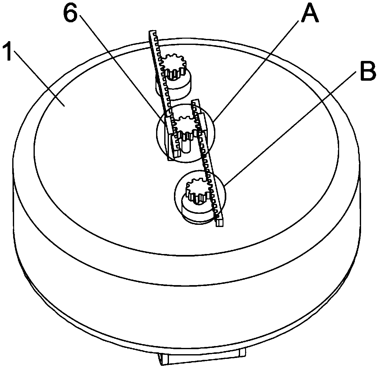
[0053] Embodiment 2 Please refer to Figure 4-6 , the steering device 6 includes a reversing motor 25, a connecting shaft 26, a support block 27, a driving gear 28 and a transmission rack 29, the reversing motor 25 is fixed on the inner wall of the buoy 1 top, and the reversing motor 25 The output shaft passes through the buoy 1 and is fixed to the bottom end of the connecting shaft 26, the top of the connecting shaft 26 is fixed to the driving gear 28, and the outer side of the driving gear 28 is meshed with two parallel transmission racks 29, and the two The transmission racks 29 are meshed with two driven gears 11 respectively, and the driven gears 11 are fixedly connected with the telescopic device 7 . The horizontal movement of the transmission rack 29 can drive the rotation of the driven gear 11, and the bottom of the driven gear 11 is fixed with the installation cylinder 9 through the rotating shaft 12, so that the rotation of the driven gear 11 can adjust the direction...
Embodiment 3
[0055] Embodiment three please refer to Figure 7-9 , the telescopic device 7 includes a mounting cylinder 9, a fixed plate 10, a driven gear 11, a rotating shaft 12, a telescopic motor 13, a telescopic cylinder 14, a drive block 15, a support member 16 and a lead screw 17, and the mounting cylinder 9 is perpendicular to The installation plate 2, the two ends of the installation cylinder 9 respectively pass through the top of the buoy 1 and the installation plate 2, and the installation cylinder 9 is respectively movably connected with the top of the buoy 1 and the installation plate 2, and the outside of the installation cylinder 9 passes through the support 16 is rotationally connected with the mounting plate 2, the rotating shaft 12 is fixed on the top of the mounting cylinder 9, the driven gear 11 is fixed on the top of the rotating shaft 12, and the driven gear 11 is connected to the output end of the steering device 6, the fixed The plate 10 is fixed on the upper part of...
PUM
 Abstract
Description
Claims
Application Information
 - R&D
- Intellectual Property
- Life Sciences
- Materials
- Tech Scout
- Unparalleled Data Quality
- Higher Quality Content
- 60% Fewer Hallucinations
Browse by: Latest US Patents, China's latest patents, Technical Efficacy Thesaurus, Application Domain, Technology Topic, Popular Technical Reports.
© 2025 PatSnap. All rights reserved.Legal|Privacy policy|Modern Slavery Act Transparency Statement|Sitemap|About US| Contact US: help@patsnap.com


