
Self-locking hydraulic cylinder

A hydraulic cylinder and self-locking technology, which is applied in the direction of fluid pressure actuating devices, etc., can solve the problems of poor self-locking effect and low safety factor, and achieve the effect of overcoming retraction action, high safety factor and simple structure

Active Publication Date: 2018-12-14
CHONGQING WEIQING HYDRAULIC MACHINERY CO LTD
View PDF3 Cites 6 Cited by
  • Summary
  • Abstract
  • Description
  • Claims
  • Application Information

AI Technical Summary

Problems solved by technology

[0004] The purpose of the present invention is to provide a self-locking hydraulic cylinder to overcome the problems in the prior art that the hydraulic reversing valve is used to realize self-locking, the self-locking effect is poor, and the safety factor is not high

Method used


Image

  • Self-locking hydraulic cylinder
  • Self-locking hydraulic cylinder
  • Self-locking hydraulic cylinder

Examples


Embodiment Construction

[0017] The present invention will be described in further detail below by means of specific embodiments:

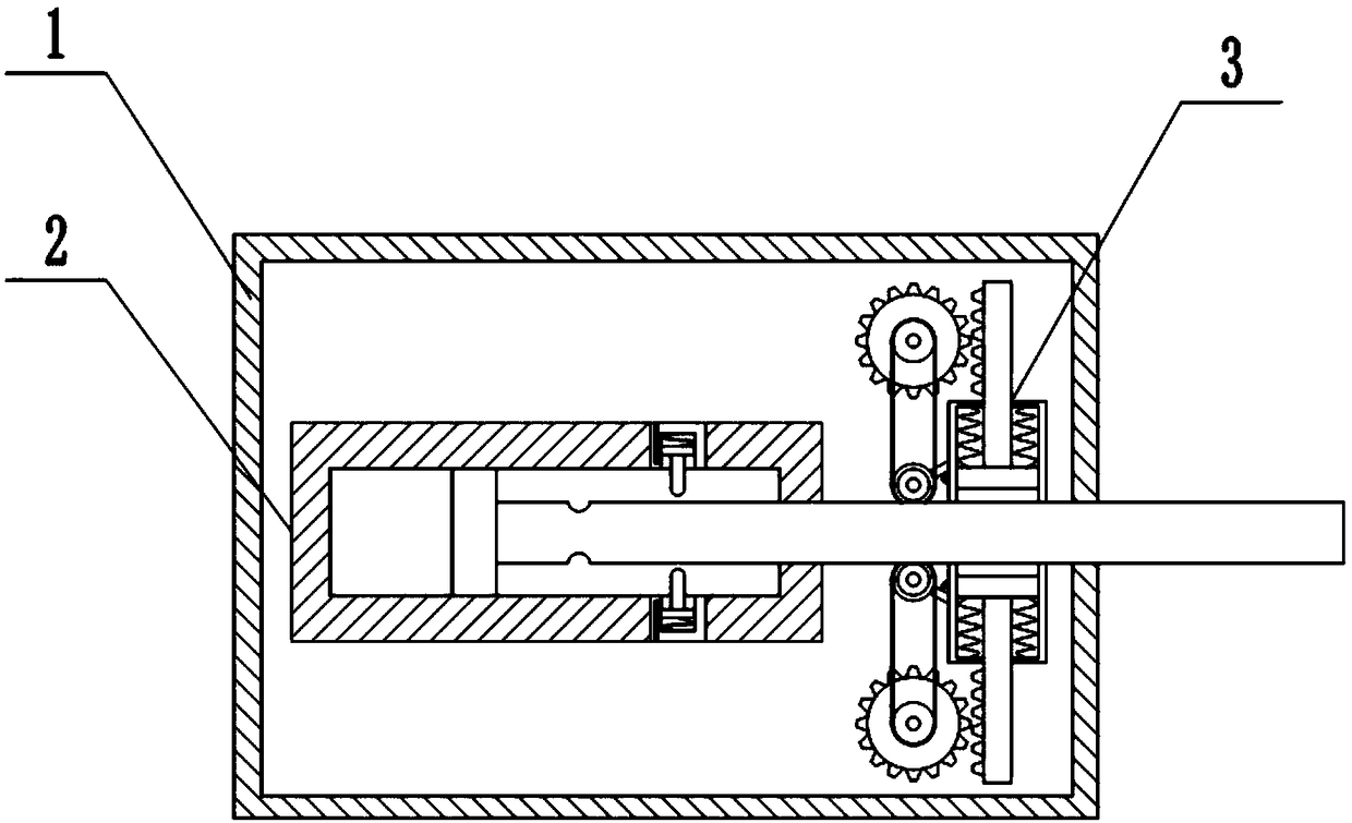
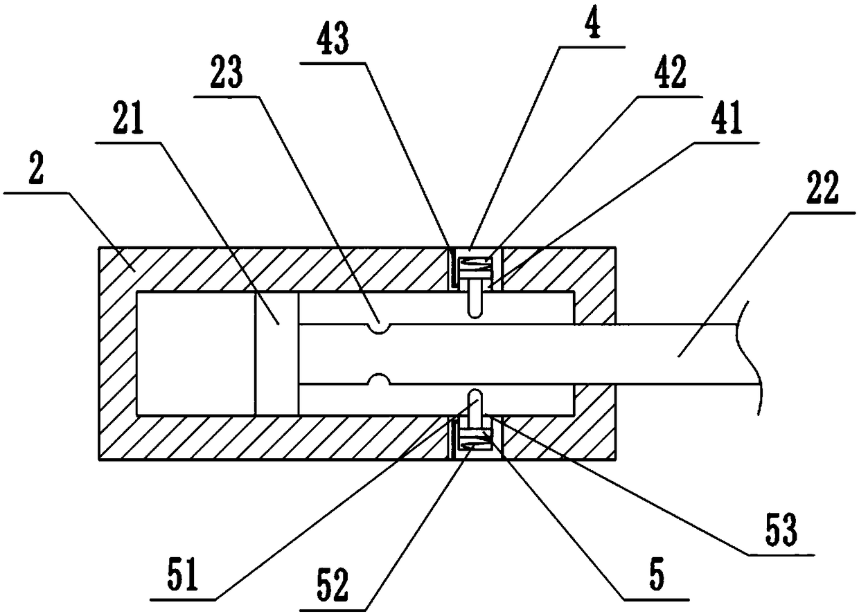
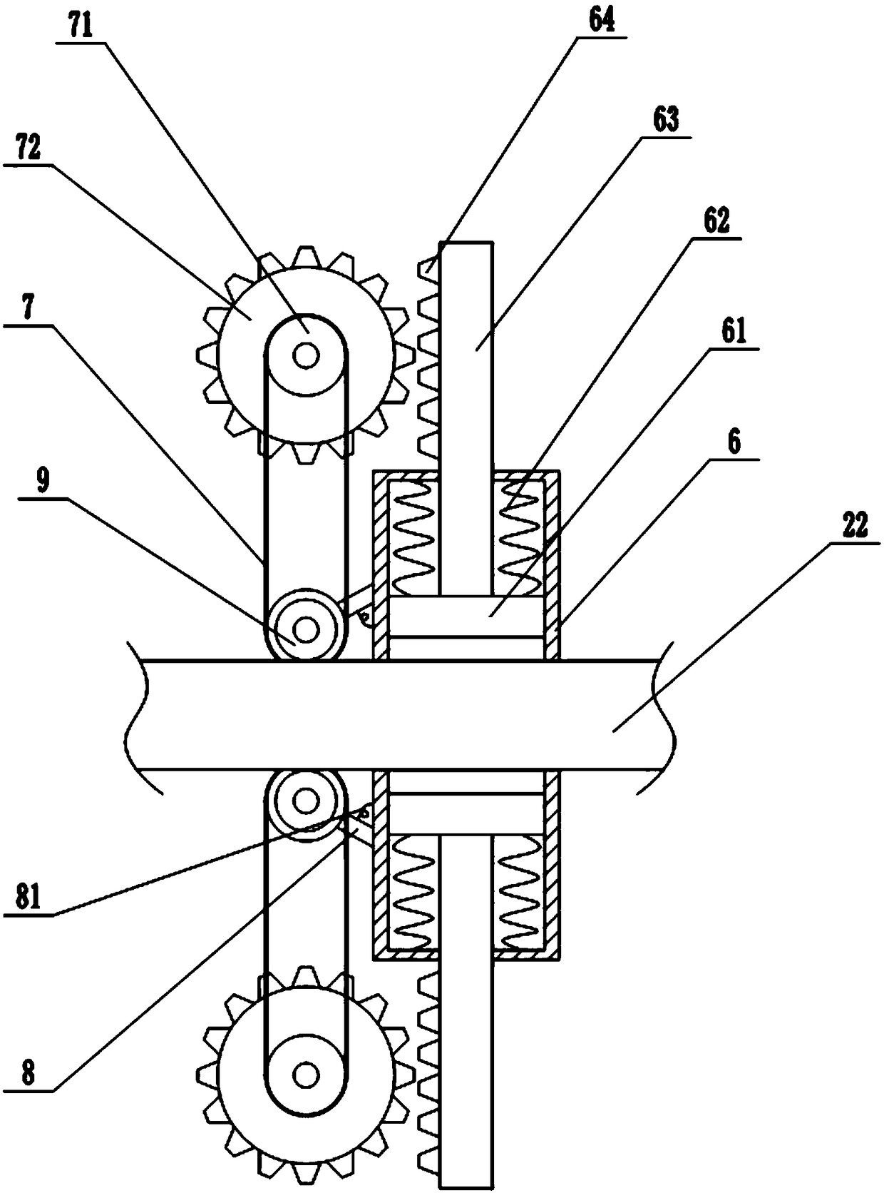
[0018] The reference signs in the accompanying drawings include: outer cylinder 1, inner cylinder 2, piston 21, piston rod 22, self-locking groove 23, locking device 3, chute 4, first chamber 41, second chamber Chamber 42, oil injection channel 43, slide plate 5, self-locking pin 51, first spring 52, sealing plate 53, frame body 6, clamping plate 61, second spring 62, support rod 63, rack 64, sprocket chain mechanism 7, sprocket wheel 71, gear 72, articulated lever 8, torsion spring 81, roller 9.

[0019] The embodiment is basically as attached Figures 1 to 3 Shown: a self-locking hydraulic cylinder, including an outer cylinder 1 , an inner cylinder 2 and a piston rod 22 , and the inner cylinder 2 is fixedly installed in the outer cylinder 1 . The inner cylinder 2 is slidingly connected with a piston 21, one end of the piston rod 22 is fixedly connected with the piston...


PUM


Abstract

The invention relates to the technical field of hydraulic equipment and discloses a self-locking hydraulic cylinder which comprises an outer cylinder barrel, an inner cylinder barrel and a piston rod;the inner wall of the inner cylinder barrel is provided with a chute; the chute is internally provided with a self-locking pin; the piston rod is provided with a self-locking groove matched with theself-locking pin; the outer cylinder barrel is internally provided with a locking device; the locking device comprises a frame body, a sprocket-chain mechanism and rolling wheels; a clamping plate anda supporting rod are connected to the interior of the frame body in a sliding manner; one end, extending out of the frame body, of the supporting rod is provided with a rack; the rolling wheels are abutted to the piston rod and are coaxially connected with one sprocket of the sprocket-chain mechanism; and a gear is coaxially connected to the other sprocket of the sprocket-chain mechanism and is mutually engaged with the rack on a supporting rod. For the hydraulic cylinder, the piston rod can have the retraction action, a locking device starts self-locking protection, and the clamping plate performs radial clamping and fixing on the piston rod, so that the retraction action of the piston rod is overcome, and the piston rod keeps stable work at the current position.

Description

technical field [0001] The invention relates to the technical field of hydraulic equipment, in particular to a self-locking hydraulic cylinder. Background technique [0002] The hydraulic cylinder is an important component widely used in the modern industrial hydraulic industry. The hydraulic cylinder is a hydraulic actuator that converts hydraulic energy into mechanical energy and performs linear reciprocating motion (or swing motion). It has a simple structure and reliable operation. When the hydraulic cylinder is used to realize the reciprocating motion, the deceleration device can be eliminated, and there is no transmission gap, and the motion is stable, so it is widely used in various mechanical hydraulic systems. [0003] When the hydraulic cylinder is working, after the piston rod of the hydraulic cylinder is extended, the piston rod needs to work stably at the current position, which can neither be extended nor retracted, which is commonly referred to as self-locking...

Claims


Application Information

Patent Timeline
IPC IPC(8): F15B15/14F15B15/26
CPCF15B15/14F15B15/26
Inventor 谷山品
Owner CHONGQING WEIQING HYDRAULIC MACHINERY CO LTD
Learn More