A Portable Stainless Steel Hole Pressing Machine

A punching machine, a portable technology, applied in the direction of feeding devices, manufacturing tools, positioning devices, etc., can solve problems such as poor matching, increased risk, and impact on use, to achieve convenient and quick fixation, convenient and quick release, and ensure safety sexual effect

Active Publication Date: 2020-08-04
新沂市智创商业管理有限公司
View PDF7 Cites 0 Cited by
  • Summary
  • Abstract
  • Description
  • Claims
  • Application Information

AI Technical Summary

Problems solved by technology

[0002] In daily life, stainless steel anti-theft windows are always installed when decorating houses. During the production process of stainless steel anti-theft windows, it is necessary to press holes in the stainless steel square pipes inserted in the middle steel pipe. The traditional pressure holes need to manually determine the middle position, and then Use a punching machine to press the holes, but sometimes the pressed holes may not match well, making it difficult to insert the steel pipe, and even affect the subsequent use. In addition, the user must fix the holes by hand, which increases the risk and consumes manpower.

Method used


Image

  • A Portable Stainless Steel Hole Pressing Machine
  • A Portable Stainless Steel Hole Pressing Machine
  • A Portable Stainless Steel Hole Pressing Machine

Examples


Embodiment Construction

[0027] The following will clearly and completely describe the technical solutions in the embodiments of the present invention with reference to the accompanying drawings in the embodiments of the present invention. Obviously, the described embodiments are only some, not all, embodiments of the present invention.

[0028] In describing the present invention, it should be understood that the terms "upper", "lower", "front", "rear", "left", "right", "top", "bottom", "inner", " The orientation or positional relationship indicated by "outside", etc. is based on the orientation or positional relationship shown in the drawings, and is only for the convenience of describing the present invention and simplifying the description, rather than indicating or implying that the referred device or element must have a specific orientation, so as to Specific orientation configurations and operations, therefore, are not to be construed as limitations on the invention.

[0029] refer to Figure ...


PUM


Abstract

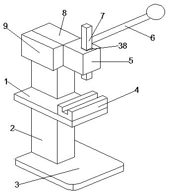
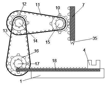
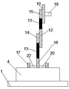
The invention discloses a portable stainless steel punching machine, and belongs to the field of stainless steel punching machines. The portable punching machine comprises a table board, the lower surface of the left side of the table board is fixedly connected with the upper end of an adjustable supporting frame, the lower end of the adjustable supporting frame is fixedly connected with the middle of the upper surface of a base, and a fixing device is arranged on the upper surface of the right side of the table board; the upper surface of the left side of the table board is fixedly connectedwith the lower surface of a linkage control device, the front side of the upper portion of the linkage control device is fixedly connected with one surface of a motor box, and the right side surface of the linkage control device is fixedly connected with the left side surface of a fixing box; and a column hole is formed in the middle of the fixing box, a straight-up gear column is arranged in thecolumn hole, the lower end of the straight-up gear column is fixedly connected with the upper end of a multi-joint drill bit, and the back surface of the fixing box is movably connected with one end of a pressing rod. According to the portable stainless steel punching machine, the linkage control device and the fixing device are arranged, so that the purposes of enabling punching to be precise during stainless steel punching and allowing a steel pipe to be conveniently inserted are achieved, and meanwhile, the effects of eliminating the danger and reducing the manpower consumption are achievedthrough the fixing device.

Description

technical field [0001] The invention relates to the field of stainless steel punching machines, in particular to a portable stainless steel punching machine. Background technique [0002] In daily life, stainless steel anti-theft windows are always installed when decorating houses. During the production process of stainless steel anti-theft windows, it is necessary to press holes in the stainless steel square pipes inserted in the middle steel pipe. The traditional pressure holes need to manually determine the middle position, and then Use a punching machine to press the holes, but sometimes the pressed holes may not match well, making it difficult to insert the steel pipe, and even affect the subsequent use. In addition, the user must fix the holes by hand when drilling, which increases the risk and consumes manpower. Contents of the invention [0003] The purpose of the present invention is to solve the problem of inaccurate, high risk and labor-intensive drilling of sta...

Claims


Application Information

Patent Timeline
IPC IPC(8): B21D28/24B21D43/00
CPCB21D28/24B21D43/003
Inventor 朱晓丹
Owner 新沂市智创商业管理有限公司
Why Eureka
Try Eureka