A lock structure of a card slot
A card slot, locking technology, applied in electrical components, telephone connectors, transmission systems, etc., can solve the problem of easy loss of mobile phone card removal pins, and achieve the effect of convenient removal of SIM cards, solving inconvenience, and protecting personal information security.
- Summary
- Abstract
- Description
- Claims
- Application Information
AI Technical Summary
Problems solved by technology
Method used
Image


Examples
Embodiment 1
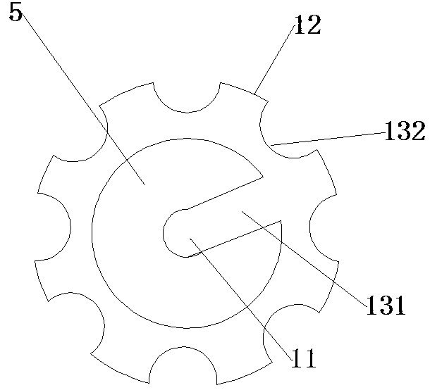
[0041] A card slot locking structure, such as figure 1 and image 3 As shown, it includes card slot 1, card tray 2, slot 3, card tray ejecting device 4 and locking device, card tray 2 is located in card slot 1, slot 3 is connected to card slot 1, and card tray ejecting device 4 is located in The bottom of the slot 3 is characterized in that the locking device includes a housing 7, a dial 5, a shaft 6, a first elastic device 8, a second elastic device 10 and a lever structure 9, and the dial 5 is located in the slot 3 Beside, there are several symbol keys 12 distributed on the outer side of the dial 5, and the symbol keys 12 are separated by grooves 132; several grooves 131 are distributed on the inner side of the dial 5, and there is a through hole 11 in the center of the dial, the grooves 131 and The through hole 11 communicates to form a passage; the shell 7 is located on the back of the mobile phone, and is consistent with the material of the bottom shell of the mobile pho...
Embodiment 2
[0045] Embodiment 2 is similar to Embodiment 1. In this embodiment, when a SIM card is installed in the mobile phone, the first elastic device 8 and the second elastic device 10 are in a compressed state, and the baffle plate 15 and the groove 131 on the dial 5 The direction of the passage position formed by the through hole 11 is inconsistent, and the baffle plate only contacts the shaft 6 but cannot pass through the dial 5 .
[0046] When you need to remove the SIM card, such as figure 2 and image 3 As shown, when the groove 131 of the dial 5 is rotated to be consistent with the position direction of the baffle 15 on the first elastic device 8, the baffle 15 passes through the groove 131, the first elastic device 8 is released, and contacts with the baffle 15 The shaft 6 is pushed inward by the first elastic device 8, and the card tray ejecting device 4 located in the slot 3 is triggered by the shaft 6 moving inward, so that the card tray 2 is ejected; at the same time, t...
Embodiment 3
[0049] Embodiment 3 is similar to Embodiment 1 and 2, and the difference is that in this embodiment, the first elastic device 8 is the first spring, the second elastic device 10 is the second spring, and the symbol key 12 on the dial 5 is number key.
[0050] A card slot locking structure, comprising a card slot 1, a card tray 2, a slot 3, a card tray pop-up device 4 and a locking device, the card tray 2 is located in the card slot 1, the slot 3 is connected to the card slot 1, and the card slot 3 is connected to the card slot 1. The tray pop-up device 4 is located at the bottom of the slot 3, and it is characterized in that the locking device includes a housing 7, a dial 5, a shaft 6, a first spring, a second spring and a lever structure 9, and the dial 5 is ring-shaped, Beside the slot 3, there are several number keys distributed on the outer side of the dial 5, and the number keys are separated by grooves 132. The numbers on the number keys are 0-7, and there is a groove 13...
PUM
 Abstract
Description
Claims
Application Information
 - R&D
- Intellectual Property
- Life Sciences
- Materials
- Tech Scout
- Unparalleled Data Quality
- Higher Quality Content
- 60% Fewer Hallucinations
Browse by: Latest US Patents, China's latest patents, Technical Efficacy Thesaurus, Application Domain, Technology Topic, Popular Technical Reports.
© 2025 PatSnap. All rights reserved.Legal|Privacy policy|Modern Slavery Act Transparency Statement|Sitemap|About US| Contact US: help@patsnap.com