
Display device and voltage regulation method thereof

A technology for voltage regulation and display devices, applied in static indicators, instruments, etc., to solve problems such as screen flickering

Active Publication Date: 2021-09-14
HKC CORP LTD +1
View PDF13 Cites 0 Cited by
  • Summary
  • Abstract
  • Description
  • Claims
  • Application Information

AI Technical Summary

Problems solved by technology

[0004] However, the working voltage used by the display panel to display images is generated by the gamma voltage generation unit. In order to meet the overvoltage driving voltage, the gamma voltage generation unit must adjust the voltage value of each line connected to the display panel, and then With the extension of use time, the attenuation or delay of the working voltage on each line is not consistent. Although the brightness of the screen is enhanced, it is easy to cause bad problems such as screen flickering.

Method used


Image

  • Display device and voltage regulation method thereof
  • Display device and voltage regulation method thereof
  • Display device and voltage regulation method thereof

Examples


Embodiment Construction

[0040] The following descriptions of the various embodiments refer to the accompanying drawings to illustrate specific embodiments in which the present invention can be practiced. The directional terms mentioned in the present invention, such as "up", "down", "front", "back", "left", "right", "inside", "outside", "side", etc., are for reference only The orientation of the attached schema. Therefore, the directional terms used are used to illustrate and understand the present invention, but not to limit the present invention.

[0041] The drawings and descriptions are to be regarded as illustrative in nature and not restrictive. In the figures, structurally similar units are denoted by the same reference numerals. In addition, the size and thickness of each component shown in the drawings are arbitrarily shown for understanding and ease of description, but the present invention is not limited thereto.

[0042] In the drawings, for clarity, the thickness of layers, films, pan...


PUM


Abstract

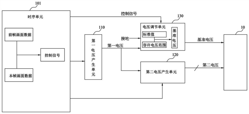
The present application relates to a display device and a voltage regulating method thereof. The display device includes: a display panel; a first voltage generation unit generates a first voltage; a second voltage generation unit generates a second voltage to the display panel according to a reference voltage; a voltage adjustment unit generates a reference voltage to the display panel according to the first voltage a timing unit electrically coupled to the above-mentioned elements; wherein, the timing unit compares the previous frame picture data with the current frame picture data, and controls the voltage adjustment unit according to the comparison result, and the voltage adjustment unit is controlled to adjust the The above reference voltage is within the specified range.

Description

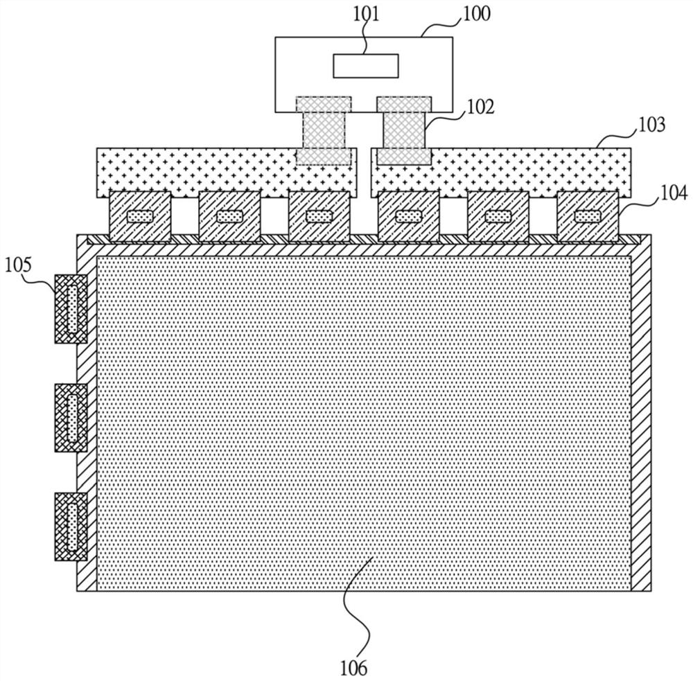
technical field [0001] The present application relates to a voltage regulation technology of a display device, in particular to a display device and a voltage regulation method thereof. Background technique [0002] In the display, the main board of the system is connected to the control board (Control Board, C-Board) through lines, and the control board is connected to the printed circuit board (PCB) through a flexible flat cable (Flexible Flat Cable, FFC). The source-chip on film (S-COF) and the gate-chip on film (Gate-chip on film, G-COF) are connected to the display area. The display driving method includes: the system main board transmits the color (for example: R / G / B) compressed signal, control signal and power to the control board. After the signal is processed by the timing controller (TCON), it is transmitted to the source driver circuit (Source Driver) and the gate driver circuit (Gate Driver). The necessary data and power are transmitted to the display area thro...

Claims


Application Information

Patent Timeline
Patent Type & Authority Patents(China)
IPC IPC(8): G09G3/36
CPCG09G3/3696
Inventor 李汶欣郭东胜
Owner HKC CORP LTD
Learn More