
Attaching device, attaching system and attaching method

A sticking and air pressure technology, applied in nonlinear optics, instruments, optics, etc., can solve the problems of affecting the sticking effect, the breakage of the adhesive tape, and the difficulty of product breakage, so as to ensure the quality of the sticker, prevent the The effect of crushing

Inactive Publication Date: 2018-12-11
WUHAN CHINA STAR OPTOELECTRONICS SEMICON DISPLAY TECH CO LTD
View PDF7 Cites 0 Cited by
  • Summary
  • Abstract
  • Description
  • Claims
  • Application Information

AI Technical Summary

Problems solved by technology

[0002] With the advancement of display technology, OLED flexible display screens have gradually become the mainstream. In the manufacturing process of flexible OLEDs, it is necessary to attach a variety of tapes at different positions. Due to uneven glue coating and design reasons, it is easy to cause the tape There is a gap at the place, which will affect the attachment effect or damage the components
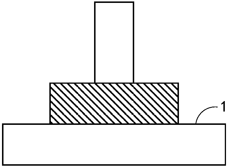
[0003] The design of the existing adhesive tape attachment mechanism is as follows: Figure 1a ~ Figure 1b As shown, among them, Figure 1a It is an ordinary stage-type attachment head, and the material of the pressure head unit 1 is selected according to the lamination requirements (soft or hard material). The hard material can be used for most products with better flatness, and the design is simple and the cost is low. However, for existing Products with gaps are difficult to deal with; soft materials (such as sponge) can be used to deal with products with gaps, but due to the problem of different deformations, there is a risk of crushing components. It can be used for products that do not need to worry about crushing at the attachment
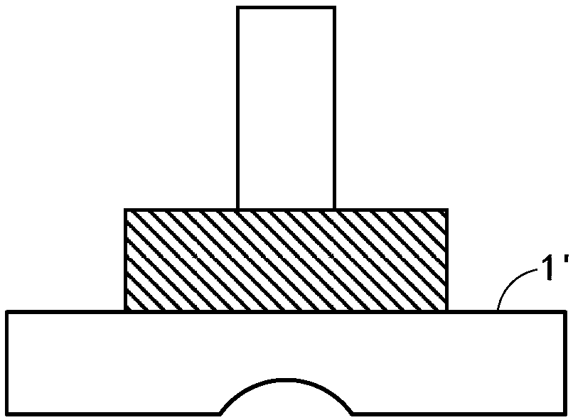
Figure 1b It is a profiling stage, and the material of the indenter unit 1' can be selected according to the lamination requirements (soft or hard material); and the profiling of the indenter unit 1' can be customized for specific products, which can deal with specific gap products, but for different It is cumbersome to change the type of the gap product, resulting in high cost

Method used


Image

  • Attaching device, attaching system and attaching method
  • Attaching device, attaching system and attaching method
  • Attaching device, attaching system and attaching method

Examples


Embodiment Construction

[0026] The present invention will be described in detail below in conjunction with the accompanying drawings and embodiments.

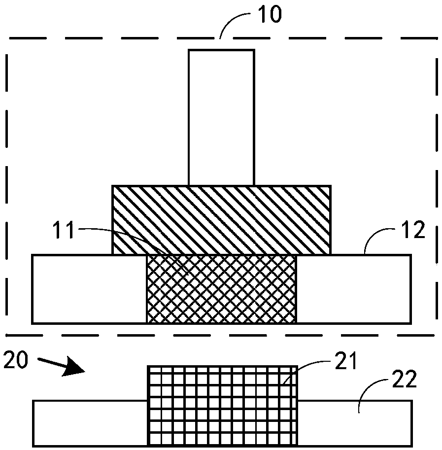
[0027] see figure 2 , is a schematic structural view of the attachment device of the present invention, the attachment device includes: an attachment head 10, and the attachment head 10 includes:

[0028] An indenter unit 11, the indenter unit 11 is made of a soft material, and is used to apply 21 an adhesive force to the first area on the product 20 to be attached;

[0029] The air pressure unit 12 outputs air, and is used to provide air pressure to exert an adhesive force on the second area 22 on the product 20 to be attached.

[0030] In this embodiment, the cross section of the attaching head 10 is circular, and may have other shapes in other embodiments, which are not limited here. Wherein, the air pressure unit 12 is adjacent to the pressure head unit 11 (such as Figure 3a shown); or two air pressure units 12 are respectively arranged on bo...


PUM


Abstract

The invention discloses an attaching device which comprises an attaching head. The attaching head comprises a pressure head unit and an air pressure unit, wherein the pressure head unit is made of soft materials and used for applying attaching force to a first area on a product to be attached, the air pressure unit outputs gas and is used for providing air pressure for applying attaching force toa second area on the product to be attached. The invention further discloses an attaching system and an attaching method. Attaching requirements are met by the mode, attaching quality is ensured, pressure injury is prevented, and a mismatch area of the product to be attached can be attached.

Description

technical field [0001] The present invention relates to the technical field of display panel manufacturing, in particular to an attaching device, an attaching system and an attaching method. Background technique [0002] With the advancement of display technology, OLED flexible display screens have gradually become the mainstream. In the manufacturing process of flexible OLEDs, it is necessary to attach a variety of tapes at different positions. Due to uneven glue coating and design reasons, it is easy to cause the tape There is a gap at the place, which will affect the attachment effect or damage the components. [0003] The design of the existing adhesive tape attachment mechanism is as follows: Figure 1a ~ Figure 1b As shown, among them, Figure 1a It is an ordinary stage-type attachment head, and the material of the pressure head unit 1 is selected according to the lamination requirements (soft or hard material). The hard material can be used for most products with bet...

Claims


Application Information

Patent Timeline
IPC IPC(8): G02F1/13
CPCG02F1/1303
Inventor 杨贵湖
Owner WUHAN CHINA STAR OPTOELECTRONICS SEMICON DISPLAY TECH CO LTD
Learn More